
Instruction Manual


016-559-B0-001 Rev. A
16
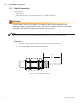
Fig. 2-8, RF Module Installation
2.0 Installation, continued
2.6 RF Module Reinstallation
Tools Required:
• No. 2. Flat head screwdriver
• Torque screwdriver
Procedure:
1. Firmly seat the module over the seizure connectors, with the open side facing AWAY from
the circuit board.
2. Tighten the captive screws to 18 in-lbs.
3. Connect the Molex connectors (Output, J4, Input, J5). Ensure that the output connector is
plugged into J4 and the input connector is plugged into J5.
The enclosure may become electrifi ed if mis-wired or in the event of an internal short.
Measure the voltage between the enclosure and earth ground before touching with bare
hands.
WARNING!
Captive Screws
Reconnect per step 3
Reconnect per step 3