Cable Series APU Control Module (ACM) Operation and Maintenance Manual Effective: February 2010 Alpha Technologies
Power Alpha Technologies ®
APU Control Module Operation and Maintenance Manual 018-340-B0-001, Rev. A Effective Date: February, 2010 Copyright© 2010 Alpha Technologies, Inc. member of The GroupTM NOTE: Photographs contained in this manual are for illustrative purposes only. These photographs may not match your installation. NOTE: Operator is cautioned to review the drawings and illustrations contained in this manual before proceeding.
Table of Contents Safety Notes .......................................................................................................................... 6 Battery Notes ......................................................................................................................... 7 1.0 System Overview ........................................................................................................ 8 1.1 Introduction ........................................................................
Figures and Tables Fig. 2-1, CPS-6 Configuration............................................................................ 11 Fig. 2-1, A2304 Dip Switch Configuration .......................................................... 12 Fig. 2-2, Y Alarms Harness ................................................................................ 12 Fig. 2-3, Alarms Jumper .................................................................................... 12 Fig. 2-4, 5-Position APS-CP Dip Switch ...................
Safety Notes Review the drawings and illustrations contained in this manual before proceeding. If there are any questions regarding the safe installation or operation of this product, contact Alpha Technologies or the nearest Alpha representative. Save this document for future reference. To reduce the risk of injury or death, and to ensure the continued safe operation of this product, the following symbols have been placed throughout this manual. Where these symbols appear, use extra care and attention.
Battery Safety Notes • Always refer to the battery manufacturer’s recommendation for selecting correct “FLOAT” and “ACCEPT” charge voltages. Failure to do so can damage the batteries. • Verify the Power Supply’s battery charger “FLOAT” and “ACCEPT” charger voltage settings. • Batteries are temperature sensitive.
1.0 System Overview 1.1 Introduction The primary purpose of Alpha’s APU Control Module (ACM) is to control and monitor generator systems that utilize the ACU Module. Depending upon the standby powering configuration, the ACM and generator combination are installed remotely, or co-located, with other Alpha equipment such as power supplies and batteries. The ACM monitors AC line and DC bus status to determine when to start and stop the APU.
1.0 System Overview, continued 1.2 Theory of Operation 1.2.1 Normal Operating Condition Under normal operating conditions (no alarms) the ACM’s Run-Auto-Stop (RAS) three position rocker switch will be in one of two positions: “AUTO” or “RUN”. (See Section 3, Indicators, Controls and Connectors) The ACM has control over the starting and stopping of the APU while in the AUTO mode.
1.0 System Overview, continued 1.2 Theory of Operation, continued 1.2.4 Normal APU Shutdown The ACM will initiate a normal APU shutdown when AC line is qualified, DC bus alarm is not active, the 12 minute cool-down period has elapsed, and the Engine Run command is not active. Otherwise, the ACM will continue to run the APU until the above conditions are met or a major alarm occurs.
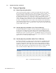
2.0 Installation, Configuration and System Interface 2.1 Field Installation 1. Disconnect all connectors from front of ACU. 2. Remove 4 screws from ACU mounting ears 3. Install ACM in place of ACU; install 4 mounting screws to secure ACM to rack and rail. 4. Connect ACM using existing cable assemblies Fig. 2-1, CPS-6 Configuration 018-340-B0-001 Rev.
2.0 Installation, Configuration and System Interface, continued 2.2 ACM-96 and ACM-96G 2.2.1 A2304 Generator Controller Configuration 1. The A2034 logic board is located in the electronics compartment of the APU enclosure. Locate the 4-position Dip Switch and set switch 2 in the OFF position. For the new configuration, switches 1 and 3 should be on, and switches 2 and 4 should be off. Fig. 2-2, A2304 Dip Switch Configuration 2.
2.0 Installation, Configuration and System Interface, continued 2.2 ACM-96 and ACM-96G, continued 2.2.2 APS-CP Generator Controller Configuration Locate the Dip Switch on the APS-CP by removing the screws in the bottom corners and lifting the front cover. If it is a 5-position Dip Switch, set switches 1 and 5 to the ON position. Fig. 2-5, 5-Position APS-CP Dip Switch If it is a 4-position Dip Switch, leave default switch positions. 2.2.
3.0 Indicators, Controls and Connectors 8 7 6 9 54 3 2 1 10 11 12 13 Fig. 3-1, ACM Front Panel APU Control Module LED Indicators and switches: 1. “Major” Alarm Indicator (Red LED) 2. “Minor” Alarm Indicator (Red LED) 3. “Notify” Indicator (Amber LED) 4. “Comm” Indicator (Green LED) 5. “System” Indicator (Green LED) 6. “Run-Auto-Stop” Switch 7. “Service/Reset” Push Button Switch 8. Analog Alarms Output 9. Communications Interface 10. Alarm: Input Signals 11. Remote: DCIU Breaker Trip 12.
3.0 Indicators, Controls and Connectors, continued 3.1 Indicators The Major and Minor alarm LEDs (1, 2) are red and reflect the state of the discrete major and minor alarms monitored by the ACM. A Major alarm indicates failure of a critical component or some other situation (pad shear, for example) where the system either has gone off-line, or system failure and/or shutdown is imminent. Major alarms cause the engine to shutdown immediately and generally prevent further operation.
3.0 Indicators, Controls and Connectors, continued 3.2 Control Functions RUN-AUTO-STOP Switch: The three positions of the rocker switch (6) are RUN, AUTO and STOP (RAS). The RAS switch is normally left in the center, AUTO, position so that the ACM has control of the generator set. A minor alarm is indicated when the RAS switch is not in the AUTO position. The STOP (“left”) position is used to stop or prevent APU operation during maintenance.
4.0 Alarms and Notifications 4.1 Alarms The ACM is capable of reporting “Major” alarms, “Minor” alarms and “Notifications”. The following are detailed descriptions of each. Major 1 2 3 4 5 6 7 8 9 10 11 12 13 14 15 1. Engine Over-Temp (OT) 9. Self-Test Fail (TF) Abbreviation OT DT OC GH WI PS LP CF TF IB AD TP DC LF SR 2. DCIU Breaker Trip (DT) 10. Low Ignition Battery (IB) Major 3. Engine Over-Crank (OC) 11. Auto-mode Disabled (AD) Minor 4. Gas Hazard (GH)* 12.
4.0 Alarms and Notifications, continued 4.1 Alarms, continued 6. Pad Shear (PS) (Latching): Indicates that the main or fuel enclosure has shifted from its pad mounting position. APU operation is suspended. The alarm is reset when the unit is returned to its original position and the reset command is issued or when the manual stop switch is activated. NOTE: APU will not start if Pad Shear magnet is not correctly installed below the Pad Shear sensor. 7.
4.0 Alarms and Notifications, continued 4.2 Notifications Additionally, the ACM will report the following “Notification” information. 14. Line Failure (LF): The ACM’s determination of the state of AC line voltage. Loss of AC utility input is one of the criteria for starting the generator. When replacing the Genasys ACU this is a 240vac sense voltage. When replacing the ACU for the distributive 2.7kw 36Vdc APU or 3.0kw 48Vdc APU it is a 120Vac sense voltage.
4.0 Alarms and Notifications, continued 4.3 Analog Transponder Interface The ACM also provides a transponder interface for proprietary status monitoring. The transponder interface consists of a 12-position terminal block wtih 8 optically-isolated output signals and one switch closure input signal. The wiring diagram for the transponder interface is shown in Fig. 4-3, with the following signals mapped to the transponder interface terminal block as shown below.
4.0 Alarms and Notifications, continued 4.
4.0 Alarms and Notifications, continued 4.5 Transponder System Block Diagram Alpha XMS2 USM-2 Transponder USM Interface Connector Enclosure Tamper Switch APU Interface 'Alpha' Side 'Transponder' Side Power Supply Enclosure Transponder to ACM Interface Cable Enclosure Sensors ACM Battery Pack, 36Vdc or 48Vdc Auxiliary Power Unit Alpha Auxiliary Power Unit (APU) Fig. 4-5, Transponder System Block Diagram 22 018-340-B0-001 Rev.
4.0 Alarms and Notifications, continued 4.6 DOCSIS Transponder Interface ACM to SCM Interface (Alpha P/N 704-709-20) ACM XM2 “Master” XM2 XM2 System Port To COMM Port STAT Communications Port S Y S S Y S C O M C O M System Port Communications Port ALM RDY COM LNK RF REG DS TMPR C O M Communications Port Battery String Connector To Battery Sense Wire Harness LOCAL Connections Connections with more than one power supply Fig. 4-6, System Interconnection Diagram 018-340-B0-001 Rev.
5.0 System Self-Test and Maintenance 5.1 Self-Test Generator testing can be initiated in four ways: 1. The ACM can be programmed to periodically run an automatic test (Default OFF). 2. A Self-Test can be commanded via status communications. 3. Momentary activation of the Engine Run command will cause the ACM to effectively run a test. Note that this method is the least desirable because the Self-Test Fail alarm will not be set if an alarm condition arises. 4.
5.0 System Self-Test and Maintenance, continued 5.1 Self-Test, continued If AC line should fail during a test, the test will terminate normally but the engine will continue to run until line returns. If the test fails because the DC Bus alarm activates, the test will terminate, the self-test fail alarm will activate but the generator will continue to run until the DC Bus alarm clears. The Self-Test Fail alarm may be cleared via a reset command or by successfully running a subsequent test.
5.0 System Self-Test and Maintenance, continued 5.2 System Maintenance The ACM monitors time between periodic maintenance of the engine-generator. The Service Interval internal ACM variable represents the number of hours of engine-run-time between periodic services. When the engine runs for a number of hours equal to Service Interval, the ACM sets the Service Required Alarm and turns on the amber notification LED. The default value of Service Interval is 100 hours.
5.0 System Self-Test and Maintenance, continued 5.2 System Maintenance, continued Power Node/ACM Certification Power Node Location___________Node____________ Model#____________ Technician______________Date ____________ Serial #___________ Ignition Battery Check (Record Results) Verify correct Ignition Battery and Charger cables attachment ...........................................................
018-340-B0-001 Rev.
018-340-B0-001 Rev.
Power Alpha Technologies ® Alpha Technologies 3767 Alpha Way Bellingham, WA 98226 USA Tel: +1 360 647 2360 Fax: +1 360 671 4936 Web: www.alpha.com Alpha Technologies Ltd. 7700 Riverfront Gate Burnaby, BC, V5J 5M4 CANADA Tel: +1 800 667 8743 Fax: +1 604 436 1233 Alpha Technologies Europe Ltd.