Operator's Manual APC Series APL Series NON-STANDBY FROM ©1996 Alpha Technologies ALPHA POWER SUPPLIES TECHNOLOGIES
APC AND APL SERIES NON-STANDBY POWER SUPPLIES IMPORTANT SAFETY INSTRUCTIONS CONTAINED IN THIS MANUAL CAUTION RISK OF ELECTRICAL SHOCK CAUTION: TO REDUCE THE RISK OF ELECTRICAL SHOCK, AND ENSURE THE SAFE OPERATION OF THIS UNIT, THE FOLLOWING SYMBOLS HAVE BEEN PLACED THROUGHOUT THE MANUAL. WHERE THESE SYMBOLS APPEAR, SERVICING SHOULD BE PERFORMED ONLY BY QUALIFIED PERSONNEL. DANGEROUS VOLTAGE A DANGEROUS VOLTAGE EXISTS IN THIS AREA. USE EXTREME CAUTION. ATTENTION IMPORTANT OPERATING INSTRUCTIONS.
APC SERIES NON-STANDBY POWER SUPPLIES ii
APC SERIES NON-STANDBY POWER SUPPLIES Table of Contents 1. 1.1 INTRODUCTION The APC (APL) Non-Standby Power Supply 1 1.2 Operating Principle 2 1.3 1.3.1 1.3.2 1.3.3 1.3.4 1.3.5 1.3.6 1.3.7 Standard Features APC (APL) 6008 APC (APL) 6014 APC (APL) 6008 E APC (APL) 6014 E APC 4808 E APC 6008 P APC 6014 P 3 3 3 3 3 3 3 3 1.4 1.4.1 1.4.2 1.4.3 1.4.4 1.4.5 1.4.6 Optional Features SIL-C LA-M AMM-C TDR-M ACAT-3P GLK 5 5 5 5 5 5 6 2. 2.1 2.2 2.2.1 2.2.2 2.3 2.4 2.5 2.
APC SERIES NON-STANDBY POWER SUPPLIES Table of Contents 3.0 3.1 3.2 OPERATION Start-up and Testing APC Shutdown and MTA Removal 34 34 35 4.0 4.1 4.1.1 4.1.2 4.1.3 4.1.4 4.1.5 TROUBLESHOOTING Troubleshooting and Repair Troubleshooting Guide Repair Instructions Parts and Ordering Information Replacement Parts Schematic / Block Diagram 36 36 36 37 37 37 38 5.0 SPECIFICATIONS 39 6.
1. INTRODUCTION 1.1 The APC (APL) Non-Standby Power Supply Product Description: Alpha APC (APL) Series non-standby power supplies provide conditioned power to signal amplifiers in Cable Television and Broadband distribution systems. The modular design, which consists of a baseplate, transformer assembly and enclosure cover, supplies the load with current-limited, regulated AC power that is free from disturbances caused by spikes, surges and other forms of power line transients.
1. INTRODUCTION 1.2 Operating Principle The Modular Transformer Assembly (MTA) contains a ferroresonant transformer, resonant circuit capacitor, and control panel with line input circuit breaker and output fuse assembly. Alpha APC (APL) Series non-standby power supplies utilize ferroresonant transformer technology to provide line conditioning and voltage regulation.
1. INTRODUCTION 1.3 Standard Features The APC (APL) Series non-standby power supplies are available in the following configurations: 1.3.1 APC (APL) 6008 Non-Standby Power Supply (120 VAC, 60 Hz Input) (8 Amp, 480 VA, 60 Volt Output); available in Pole, Rack, Wall, Shelf, or Pedestal-mount configurations. Includes: 8 Amp thermal input circuit breaker, 120 VAC output receptacle and 10 Amp output fuse. 1.3.
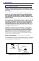
1. INTRODUCTION 1.3 Standard Features, continued Main Transformer Assembly (MTA) Enclosure Cover Baseplate Assembly Pad-Lock Holes Photo 1.3.a Pole Mount Enclosure Photo 1.3.b APC Main Transformer Assembly Photo 1.3.
1. INTRODUCTION 1.4 Optional Features APC (APL) Series non-standby power supplies can also be equipped with the following options: 1.4.1 SIL-C (Status Indicator LED) The Status Indicator LED (red) indicates that the APC (APL) is supplying AC output to the load. The long-life LED pilot lamp can be viewed from outside the enclosure. As long as power is present at the modules output, the lamp remains ON.
1. INTRODUCTION 1.4 Optional Features, continued 1.4.6 GLK (Enclosure Locks) APC (APL) Pole Mount enclosures can be equipped with an optional security lock in situations where accessibility or tampering may be a problem. PM models come equipped with a security hole for installing a standard padlock (see figure 1.3.a).
2. INSTALLATION 2.1 Unpacking and Inspection To ensure operator safety: 1. Power supplies should be installed only by qualified personnel and always in accordance with applicable electrical codes. 2. Use a bucket truck or suitable climbing equipment, such as safety harness and spikes, whenever installing pole-mount installations. 2.1 Unpacking and Inspection Carefully remove the APC from its shipping container. Make sure that the following items have been included: 1. 2. 3.
2. INSTALLATION 2.2 Pole-mount Installations The APC- PM and APL-PM are designed to be mounted on wooden, steel, or concrete poles. When used with wooden poles, mounting bolts that go completely through the pole should be used. When used with concrete poles, an approved mounting strap should be used. Most codes require the base of the enclosure to be located at a minimum height from the ground. Always verify height restrictions before proceeding.
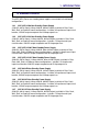
2. INSTALLATION 2.2 Pole-mount Installations, continued Service Drop Enclosure Mounting Bracket 5/8” Diameter Bolts and Associated Hardware APC (APL) Enclosure NOTE: If mounting to a steel or concrete pole, use these two strap slots 4.5” center-center Utility Power Input (from Service Entrance) VSF Output Connector 60 VAC Cable Output #8 AWG (Minimum) Copper Ground Wire To Service Entrance Illustration 2.
2. INSTALLATION 2.2 Pole-mount Installations, continued 2.2.2 Concrete and Steel Poles Materials Required: Two (2) 1-1/2” mounting straps, length to suit pole. Tools Required: Assorted sockets or wrenches. Procedure: 1. Mark the position for the upper mounting strap on the utility pole. 2. Run two, approved 1-1/2” mounting straps through the mounting bracket located on the back of the baseplate assembly. 3. Center the baseplate assembly on the pole and tighten the mounting straps. 4.
2. INSTALLATION 2.3 Wall-mount Installations The wall-mount version is equipped with an adaptor bracket allowing the APC or APL pole-mount enclosure to be mounted on a flat, vertical surface. NOTE: BEFORE INSTALLING THE MTA, ENSURE THAT ALL OPTIONS HAVE BEEN INSTALLED AND PROPERLY CONNECTED. REFER TO SECTION 2.11 OPTIONS, FOR INSTALLATION PROCEDURES. Procedure: 1. Mount the wall-mount bracket to a flat vertical surface.
2. INSTALLATION 2.4 Pedestal-mount Installations The pedestal-mount (PED) is constructed of weather-resistant steel and is ideal for ground mount applications. The PED model is supplied with a stake for soilmounting applications, an optional concrete mounting kit may be ordered for mounting to a concrete pad. NOTE: BEFORE INSTALLING THE MTA, ENSURE THAT ALL OPTIONS HAVE BEEN INSTALLED AND PROPERLY CONNECTED.
2. INSTALLATION 2.4 Pedestal-mount Installations, continued Poured Concrete Detail showing mounting stake and hardware Photo 2.4.a Stake Mounting Cable Utility Mounting Stake Photo 2.4.b Poured Concrete Illustration 2.
2. INSTALLATION 2.4 Pedestal-mount Installations, continued Procedure: (concrete-mount version) Illustration 2.4; Photos 2.4.c, .d The PED enclosure can be mounted to a concrete pad using the optional mounting bracket. The bracket is mounted inside the rear of the enclosure using two (2) hex bolts and washers. Two (2) 0.5” oblong mounting holes are provided in the bracket to mount the enclosure to the concrete pad.
2. INSTALLATION 2.5 Rack-mount Installations The APC is also available in a rack-mount version that can be installed into a standard 19” rack. The APL is not available in a rack-mount model. NOTE: BEFORE INSTALLING THE APC, ENSURE THAT ALL OPTIONS HAVE BEEN INSTALLED AND PROPERLY CONNECTED. REFER TO SECTION 2.11 OPTIONS, FOR INSTALLATION INSTRUCTIONS. Procedure: Photo 2.5.a 1.
2. INSTALLATION 2.5 Rack-mount Installations, continued TDR-M LA-P receptacle ACAT-3P 3-pin connector Output connector (60 VAC) 2-pin connector Power input cord Shorting connector Photo 2.5.b Option placement and power connections Photo 2.5.
2. INSTALLATION 2.6 Shelf-mount Installations The shelf-mount version of the APC (APL) consists of the standard MTA (Modular Transformer Assembly) which rests on a mounting plate (SM). The mounting plate and MTA can then be installed into an enclosure such as the PED- M, PWE or UPE. The shelf-mount option also includes an input AC power extension cable (APC model only) and an APC - SPI adaptor. NOTE: BEFORE INSTALLING THE APC, ENSURE THAT ALL OPTIONS HAVE BEEN INSTALLED AND PROPERLY CONNECTED.
2. INSTALLATION 2.6 Shelf-mount Installations, continued Hold-down screw APC Output to Terminal Block Photo 2.6.b PED-M, PWE or UPE Enclosure Mounting (using Terminal Block Output) APC Output to SPI (via SPI adaptor cable) Hold-down screw Photo 2.6.
2. INSTALLATION 2.7 Connecting Utility Power CAUTION: THE FOLLOWING SHOULD BE PERFORMED ONLY BY QUALIFIED SERVICE PERSONNEL AND IN COMPLIANCE WITH LOCAL ELECTRICAL CODES. CONNECTION TO UTILITY POWER MUST BE APPROVED BY THE LOCAL UTILITY BEFORE INSTALLING THE POWER SUPPLY. NOTE: UL AND NEC REQUIRE THAT A SERVICE DISCONNECT SWITCH (UL LISTED) BE PROVIDED BY THE INSTALLER AND BE CONNECTED BETWEEN THE POWER SOURCE AND THE ALPHA POWER SUPPLY. 2.7.1 Wiring the Enclosure’s Utility Service: Photos 2.7.1.a, .
2. INSTALLATION 2.7 Connecting Utility Power, continued 5. 6. 7. Connect the utility GREEN with YELLOW tracer GROUND wire to the grounding-wire-clamp on the baseplate and tighten the clamping screw. An external grounding clamp is also provided on the outside of the enclosure for connection to a ground-rod. Reposition the rear tab on the receptacle box into the slot in the baseplate. Tighten the two (2) captive screws. Reinstall the MTA and tighten the screw.
2. INSTALLATION 2.8 External Service Disconnect The external service disconnect should be placed between the utility power connection and the APC non-standby power supply. For pole-mount enclosures, it should be attached directly to the utility pole using 1/4” x 2-1/4” steel wood screws. If a utility power meter is to be used, its mounting base should be secured in the same manner. Use a suitable conduit to interconnect the meter base, service disconnect and power supply enclosure.
2. INSTALLATION 2.8 External Service Disconnect, continued From Utility Power Meter Socket Clamps Meter Ground Neutral Hot Service Entrance (BBX Option) (Square D Q0115 HM) Hot Neutral To APC (APL) Pole Mount Ground Hot Ground Clamp #8 AWG (Minimum) Copper Ground Wire Illustration 2.8.a Service Entrance / Meter Connections Meter Service Entrance Alpha BBX Option 5’6” 8’ Ground Rod Illustration 2.8.
2. INSTALLATION 2.9 Modular Transformer Assembly (MTA) The APC and APL’s modular transformer assembly is designed for quick installation and removal. A captive screw in the baseplate secures the MTA into the enclosure. BEFORE PROCEEDING WITH THE INSTALLATION OF THE MTA, THE ENCLOSURE MUST BE MOUNTED, AND UTILITY / CABLE LINES SHOULD BE WIRED AS PREVIOUSLY DESCRIBED IN THE MANUAL. 2.9.1 Pole-mount (PM) and Wall-mount (WM) Photo 2.9.1 Procedure: 1. Place the Modular Transformer Assembly onto the baseplate.
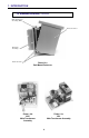
2. INSTALLATION 2.9 Modular Transformer Assembly (MTA), continued Fit tab on baseplate through slot in the MTA 60VAC Output connector Baseplate assembly Main Transformer Assembly Photo 2.9.1 MTA mounted on the baseplate assembly of a PM Enclosure MTA Mounting Tab Wing-nut Universal Bracket (UB1) APC Output Connector Receptacle Box PED Enclosure Extended Mounting Bracket Photo 2.9.
2. INSTALLATION 2.10 AC Output Connection Procedure: Photos 2.10.a, 2.10.b, 2.10.c 1. Prepare the incoming coaxial cable used for the distribution of power (including external fittings not supplied by Alpha). 2. Loosen the APC’s (APL) brass seizure screw output fitting to accommodate the center pin (“stinger”) of the cable connector. (See Photo 2.10.b). 3. Screw the cable connector into the output port (large hex nut fitting) located on the baseplate of the APC (APL), (Photo 2.10.c).
2. INSTALLATION 2.11 Options APC and APL Series non-standby power supply are designed so that options can be installed easily in the field in a minimum amount of time. NOTES: Options specified at the time of ordering will be installed by the factory. Options ordered at a later time must be installed only by qualified service personnel. Only the SIL-C; LA-L; and GLK options can be used with the APL model nonstandby power supply.
2. INSTALLATION 2.11 Options, continued 2.11.2 LA-M (Lightning Arrestor for the APC Series) Photos 2.11.2.a, 2.11.2.b The LA-M provides additional protection to sensitive electronic equipment from line disturbances caused by nearby lightning strikes, surges and spikes. The LA-M requires no hard-wiring and plugs directly into the 2-pin receptacle to the right to the APC’s power receptacle. The LA-M should be installed with the imprinted label up.
2. INSTALLATION 2.11 Options, continued Photo 2.11.2.a LA-M Inserted into Receptacle Box (PM and PED models) Photo 2.11.2.b LA-P Inserted into Receptacle (Rack-mount model) Photo 2.11.2.1 The LA-L Option for APL, Hard-wired to the Terminal Block Photo 2.11.2.
2. INSTALLATION 2.11 Options, continued 2.11.3 AMM-C (Ammeter) Photo 2.10.3 The AMM-C Ammeter displays output current to the load. This provides a visual indication of the load applied to the APC and also aids in determining if an open or short circuit condition exists. The AMM-C consists of an Ammeter, pressure mounting bracket, and an 8” connecting cable complete with spade-lug connectors. This option is not available for the APL.
2. INSTALLATION 2.11 Options, continued Remove this wire from fuse-holder Place wire on upper tab of Ammeter Photo 2.11.3.a Photo 2.11.3.b Connect wire from AMM-C kit between these tabs Optional mounting slot (for shelf mount installations) Photo 2.11.3.
2. INSTALLATION 2.11 Options, continued 2.11.4 TDR-M (Plug-in Time Delay Relay) and ACAT-3P (AMP Clamp) Photos 2.11.4.a; b The TDR-M briefly delays power to the output during utility start-ups (after an outage has occurred). The delay time can be varied between 10 and 60 seconds by using an easily accessible potentiometer. The ACAT-3P clamps dangerous spikes and surges to ground protecting sensitive electronic equipment. These options are not available for the APL.
2. INSTALLATION 2.11 Options, continued 2.11.5 Rack-mount Options The APC Rack-mount options include: ACAT-3P; TDR-M; and LA-P (LA-E for 230 VAC models). These options are mounted in a slightly different manner. CAUTION: BEFORE PROCEEDING, ENSURE THAT THE UTILITY POWER HAS BEEN DISCONNECTED! 2.11.5.1 ACAT-3P and TDR-M Photo 2.11.5.1 Procedure: 1. Mount these options on the rear of the unit and secure with one (1) SEMS screw. The screw is inserted from the front panel of the APC. See Photo 2.10.
2. INSTALLATION 2.11 Options, continued 2.11.5.3 LA-E (230VAC Models) Photo 2.11.5.3.a, .b, .c, .d Procedure: The LA-E mounts on the back of the front panel and is secured by means of the existing screw. This option must be hard-wired into the rack-mount unit by means of quick-connect connectors. 1. 2. 3. 4. Remove the wing-nut from the screw on the LA-E mounting bracket. Position the LA-E as shown in Photo 2.10.5.d and secure using the same screw.
3. OPERATION 3.1 Start-up and Test Once utility and cable connections have been made, the APC or APL should be tested before placing it into service. Procedure: Photos; APC-3.1.a; APL-3.1.b 1. Before applying power, ensure that the AC LINE circuit breaker is in the OUT (OFF) position (the white portion of the stem will be visible). If it is not, depress the breaker button all the way until it resets. 2. Plug the APC’s power plug into the receptacle provided in the internal AC receptacle box.
3. OPERATION 3.2 Shutdown and MTA Removal The modular APC and APL Series non-standby power supplies are designed for easy component removal and replacement. The entire main transformer assembly (MTA) can be replaced or upgraded in a matter of minutes. CAUTION: USE HEAVY GLOVES WHEN HANDLING A POWER MODULE THAT HAS JUST BEEN TAKEN OUT OF SERVICE. THE FERRORESONANT TRANSFORMER GENERATES HEAT AND MAY CAUSE BURNS IF HANDLED WITH BARE HANDS. Procedure: 1.
4. TROUBLESHOOTING 4.1 Troubleshooting and Repair 4.1.1 Troubleshooting Guide (Table 4.1) The troubleshooting guide is designed to display typical symptoms, causes and solutions, starting with the most obvious and working systematically through the unit. Alpha Technologies recommends that the power supply’s maintenance log accompany units brought in for bench service to aid the technician in troubleshooting the problem. Table 4.
4. TROUBLESHOOTING 4.1 Troubleshooting and Repair, continued 4.1.2 Repair Instructions Before returning a unit to Alpha Technologies for repair, a Material Authorization (RMA) should be clearly marked on the unit’s original shipping container. If the original container is no longer available, pack the unit in at least 3 inches of shock absorbent material. Do not use popcorn type material. Returns should be prepaid and insured (COD and freight collect can not be accepted).
4. TROUBLESHOOTING 4.1 Troubleshooting and Repair, continued 4.1.5 Schematic / Block Diagram The schematic / block diagram displays the main components of the APC - APL Series non-standby power supply. This diagram also shows where options are electrically installed in the circuit. For a detailed description of installing options please refer to the OPTIONS section of the manual.
5. SPECIFICATIONS Specifications Specifications: Model: APC 6008 (E) APL 6008 (E) Input Voltage (VAC): 120 (230) 120 (230) 220 220 230 Input Frequency: (Hz) 60 (50) 60 (50) 60 60 50 Input Current: (A) 3.5 (1.9) 6.2 (3.2) 2.3 3.
6. WARRANTY Warranty Warranty Alpha Technologies, Inc. provides a LIMITED WARRANTY covering the performance of its broadband products. The terms and conditions of the LIMITED WARRANTY STATEMENT are contained in a separate written LIMITED WARRANTY STATEMENT included with the Operator’s manual provided with this product. If there are any warranty claims, the purchaser (or purchaser’s representative) must follow the LIMITED WARRANTY guidelines, described in the applicable LIMITED WARRANTY STATEMENT.
USA & LATIN AMERICA Alpha Technologies 3767 Alpha Way Bellingham, WA 98226 Tel: (360) 647-2360 Fax: (360) 671-4936 CANADA & ASIA PACIFIC Alpha Technologies 7033 Antrim Avenue Burnaby, B.C. V5J 4M5 Tel: (604) 430-1476 Fax: (604) 430-8908 UNITED KINGDOM Alpha Technologies Cartel Business Estate Edinburgh Way Harlow, Essex CM20 2DU Tel: +44-1279-422110 Fax: +44-1279-423355 GERMANY Alpha Technologies Hansastrasse 8 D-91126 Schwabach Tel: +49-9122-997303 Fax: +49-9122-997321 MIDDLE EAST Alphatec P.O.