BPS Series Bypass Switch BPT Series Bypass Transformer Bypass Switches for CFR Uniterruptible Power Supplies Operator’s Manual 020-133-B0 Rev.
Power Alpha Technologies ®
Operator’s Manual BPS Series Bypass Switch BPT Series Bypass Transformer Bypass Switches for CFR Uninterruptible Power Supplies From Alpha Technologies 020-133-B0 Rev.
Save This Manual: It contains important safety instructions. Keep it in a safe place. Table of Contents 1 Safety Checklists......................................... 1 2 Introduction.................................................. 2 2.3 Bypass Switch Terminology................... 2 2.1 The Alpha Bypass Switch (BPS)............ 2 2.2 The Alpha Bypass Transformer (BPT)... 2 2.4 Bypass Switch Selection Guide)............ 4 3 Installation................................................... 6 3.
Safety Checklists 1 Safety Checklists CAUTION: Before attempting to install either the Bypass Switch or the Bypass Transformer please read the instructions contained in this manual. It provides information on how to install and test bypass switches in North America and some foreign countries. If in doubt, contact Alpha Technologies for assistance. Do not work alone under hazardous conditions. For safety reasons the installation must be carried out by qualified personnel.
The Alpha BPS Series 2 Introduction 2.1 The Alpha Bypass Switch (BPS) The Bypass Switch is a manually operated mechanical switch which is used to select an alternate source of power for critical loads should the UPS require service or maintenance. Normally the output to the critical load is powered by the UPS and the Bypass Switch is in the UPS position.
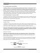
Introduction Make-Before-Break Make-Before-Break Bypass Switches provide continuous power to the load during switching. The bypass supply and the UPS output supply are momentarily connected in parallel to ensure that power to the load is not interrupted when switching. The duration of time the two supplies remain in parallel is determined by how quickly the switch is operated.
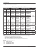
The Alpha BPS Series 2.4 Bypass Switch Selection Guide) Table 1 – Bypass Model Selection Guide Configuration CFR 3000 or Smaller CFR 4000 or CFR 5000 Input Output MBB BBM MBB BBM 120V 120V BPS 2M3P Figure 6.1 BPS 2B3P Figure 6.1 BPS 2M3P Figure 6.1 BPS 2B3P Figure 6.1 120V 120V 208V BPS 2M3P Figure 6.2 BPS 2B3P Figure 6.2 BPS 2M3P Figure 6.2 BPS 2B3P Figure 6.2 120V 120V 240V BPS 2M3P Figure 6.3 BPS 2B3P Figure 6.3 BPS 2M3P Figure 6.3 BPS 2B3P Figure 6.
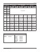
Introduction Table 1 – Bypass Model Selection Guide (Continued) Configuration CFR 7500 MBB BBM CFR 10K MBB BBM CFR 15K Input Output MBB BBM 120V 120V 120V 120V 208V 120V 120V 240V 208V 120V 208V 120V 208V BPS 2M3P BPT 15K Figure 6.7 BPS 2B3P Figure 6.6 208V 120V 240V 240V 120V BPS 2M3P Figure 6.9 BPS 2B3P Figure 6.9 BPS 2M3P Figure 6.9 BPS 2B3P Figure 6.9 BPS 2M3P Figure 6.9 BPS 2B3P Figure 6.9 240V 120V 208V BPS 2M3P BPT 3000 Figure 6.7 BPS 2B3P BPT 3000 Figure 6.
The Alpha BPS Series 3 Installation 3.1 Unpacking and Inspection Carefully inspect the contents while removing them from the shipping container. If items appear damaged or are missing, contact Alpha Technologies and the shipping company immediately. Most shipping companies have only a short claim period. Make sure the following items have been included: 1. Bypass Switch and/or a Bypass Transformer 2. Operator’s Manual 3. Any other ordered options SAVE THE ORIGINAL SHIPPING CONTAINER.
Installation 3.2 Bypass Switch Installation CAUTION: The installation and testing of the Bypass Switch must be performed only by qualified personnel familiar with installing electrical equipment. This must be done in accordance with the rules and regulations of local and national electrical codes. The installation of a bypass circuit breaker is required. To select the proper size circuit breaker refer to Table 2. Procedure: 1.
The Alpha BPS Series 3.3 Circuit Breaker Rating and Wire Guage Systems with a Bypass Isolation Transformer Installed: Install a Bypass Circuit Breaker with the current rating specified in Table 2. Use the wire gauge, as specified, for all connections to the Bypass Switch, especially if there is 208V or 240V supplied to the load. CAUTION: For UPS output configurations which supply both 120V and 208 / 240V loads, care must be taken not to overload either of the output windings of the Bypass Transformer.
Operation 4 Operation 4.1 Testing Bypass Switch Operation CAUTION: This test must first be performed with all power to the Bypass Switch turned OFF.. To test that all connections are made correctly, with all power to the bypass switch turned off, measure the resistance between pin 2 & 3, 5 & 7, and between 9 & 11 to ensure that there is no connection between the two sources of power (UPS and BYPASS).
The Alpha BPS Series 4.2 Bypass Switch Operating Procedure CAUTION: Always operate the switch with a quick continuous motion, do not hold it in mid-position. CAUTION: DO NOT operate the bypass switch while the UPS is in inverter mode (LINE FAILURE light on the front panel will be ON). BPS 3M3P Bypass Switch - Closed Bypass Switch - Open 10 Doc# 020-133-B0 Rev.
Specifications 5 Specifications 5.1 BPS Specifications KNOCK OUT MODEL A B C D E F G 2M3P, 2B3P (inches) (mm) 10.5 266 12 304 9.1 231 2 50 2 50 2 50 1.5 38 10 254 18 475 9 286 2 50 2 50 2 50 1.5 38 3M3P(inches) (mm) Bypass Switch Dimensions Due to ongoing product improvements, specifications are subject to change without notice Doc# 020-133-B0 Rev.
The Alpha BPS Series 5.
Schematic Diagrams 6. Schematic Diagrams Figure 6.1 System Bypass Schematic 120V IN - 120V OUT Doc# 020-133-B0 Rev.
NOTES: The UPS will be internally configured for either 208V or 240V. Check the nameplate rating of the UPS to verify the correct voltage. The Alpha BPS Series Figure 6.2 System Bypass Schematic 120V IN - 120V/208V OUT 14 Doc# 020-133-B0 Rev.
Doc# 020-133-B0 Rev. 01 / 07 2. Omit this connection if 120V output is not required or available. NOTES: 1. The UPS will be internally configured for either 208V or 240V. Check the nameplate rating of the UPS to verify the correct voltage. Schematic Diagrams Figure 6.
The Alpha BPS Series Figure 6.4 System Bypass Schematic 208V IN - 120V OUT 16 Doc# 020-133-B0 Rev.
Doc# 020-133-B0 Rev. 01 / 07 NOTES: 1. Terminal designatioons are shown for Standard BPT Series Bypass transformers. If BPT -S Series trandformers are used, refer to label on transformer for actual terminal designations. NOTE 1 Schematic Diagrams Figure 6.
18 2. Omit this connection if 120V output is not required or available. NOTES: 1. The UPS will be internally configured for either 208V or 240V. Check the nameplate rating of the UPS to verify the correct voltage. The Alpha BPS Series Figure 6.6 System Bypass Schematic 208V IN - 120V/208V OUT Doc# 020-133-B0 Rev.
Doc# 020-133-B0 Rev. 01 / 07 2 2 3. Terminal designations are shown for Standard VBPT Series. If BPT -S Series transformer is used, refer to label on transformer for actual terminal designations. 2. Omit this connection if 120V output is not required or available. NOTES: 1. The UPS will be internally configured for either 208V or 240V output. Check the nameplate rating of the UPS to verify the correct voltage. 1 NOTE 3 Schematic Diagrams Figure 6.
20 2 2 3. Terminal designations are shown for Standard BPT Series. If BPT -S Series transformer is used, refer to label on transformer for actual terminal designations. 2. Omit this connection if 120V output is not required or available. NOTES: 1. The UPS will be internally configured for either 208V or 240V output. Check the nameplate rating of the UPS to verify the correct voltage. 1 NOTE 3 The Alpha BPS Series Figure 6.8 System Bypass Schematic 208V IN - 120V/240V OUT Doc# 020-133-B0 Rev.
Schematic Diagrams Figure 6.9 System Bypass Schematic 240V IN - 120V OUT Doc# 020-133-B0 Rev.
22 NOTE 2 NOTE 2 3. Terminal designations are shown for Standard VBPT Series. If BPT -S Series transformer is used, refer to label on transformer for actual terminal designations. 2. Omit this connection if 120V output is not required or available. NOTES: 1. The UPS will be internally configured for either 208V or 240V output. Check the nameplate rating of the UPS to verify the correct voltage. NOTE 1 NOTE 3 The Alpha BPS Series Figure 6.
Doc# 020-133-B0 Rev. 01 / 07 2. Omit this connection if 120V output is not required or available. NOTES: 1. The UPS will be internally configured for either 208V or 240V. Check the nameplate rating of the UPS to verify the correct voltage. Schematic Diagrams Figure 6.
The Alpha BPS Series Figure 6.12 System Bypass Schematic 230V IN - 230V OUT 24 Doc# 020-133-B0 Rev.
Doc# 020-133-B0 Rev.
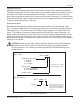
26 Utility Distribution Panel 208/120 VAC 3 Phase 208 VAC input 240/120 VAC output 25 kVA transformer 240 VAC 3 wire (L1, L2, G) 4 AWG Max Do not place transient generating equipment, such as Air Conditioning, on the UPS Automatic Transfer Switch Break Before Make with 2 second center off delay Generator 125 Amp 208VAC UPS Breakers Phase Order L1, L2 Non-critical Devices Building Lighting Air Conditioning 240/120VAC 4 wire (L1, L2, N, G) 4 AWG Max Inverter Alpha 18 KVA UPS Rectifier Static
Doc# 020-133-B0 Rev.
The Alpha BPS Series 7 Maintenance 7.1 Repair Instructions Before returning a unit to Alpha Technologies for repair, a Return Material Authorization (RMA) should first be obtained from Alpha's Customer Service Department. The RMA number should be clearly marked on the unit’s original shipping container. If the original container is no longer available, the UPS should be packed with at least 3 inches of shock-absorbent material. Note: Do not use popcorn-type packing material.
Maintenance 7.2 Warranty LIMITED 24-MONTH WARRANTY AC PRODUCTS Alpha Technologies warrants its equipment to be free of manufacturing defects in material and workmanship for a period of 24 months from the date of manufacture. The liability of Alpha Technologies under this warranty is solely limited to repairing, replacing, or issuing credit for such equipment (at the discretion of Alpha Technologies), provided that: 1.
This page is intentionally left blank.
For emergency technical support 7 days a week/24 hours a day, call: USA: 1 800 863 3364 Canada: 1 800 667 8743 Complete the following for your records Serial # _________________________________________ Options_________________________________________ Purchase Date ___________________________________ This product was purchased from Dealer__________________________________________ City_ ___________________________________________ State/Province____________________________________ Zip/Postal Code____________
Power Alpha Technologies ® Alpha Technologies 3767 Alpha Way Bellingham, WA 98226 USA Tel: +1 360 647 2360 Fax: +1 360 671 4936 Web: www.alpha.com Alpha Technologies Ltd. 4084 McConnell Court Burnaby, BC, V5A 3N7 CANADA Tel: +1 604 430 1476 Fax: +1 604 430 8908 Alpha Technologies Europe Ltd.