BSM-3 Battery Side Module Enclosure Field Upgrade Installation Manual Effective: May, 2003 ®
Power Alpha Technologies ®
Preface BSM-3 Battery Side Module Field Installation Manual 033-082-C0-002, Rev. B May, 2003 Copyright © 2003 by Alpha Technologies, Inc NOTE: Alpha denies responsibility for any damage or injury involving its enclosures, power supplies, generators, batteries, or other hardware when used for an unintended purpose, installed or operated in an unapproved manner, or improperly maintained. NOTE: Photographs contained in this manual are for illustrative purposes only.
Preface Table of Contents Preface Preface Preface Preface 1.1 1.2 1.3 1.4 1.5 1.6 Safety Instructions ..................................................... 5 Safety Precautions ..................................................... 6 Battery Safety Notes .................................................. 7 Installation Notes ....................................................... 8 BSM Installation ......................................................... 10 Tamper Switch Option ...........................
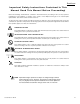
Preface Impor tant Safety Instructions Contained In This Manual Read This Manual Before Proceeding! Review the drawings and illustrations contained in this manual before proceeding. If there are any questions regarding the safe installation or operation of the system, contact Alpha Technologies or the nearest Alpha representative. Save this document for future reference.
Preface General Safety Precautions A “Warning” identifies conditions and actions that pose a hazard to the user. A “Caution” identifies conditions and actions that may damage the power supply or associated equipment. Warnings NOTE: This enclosure and its associated hardware (power supply, batteries, cabling) may contain equipment, batteries or parts which have accessible hazardous voltage or currents.
Preface Battery Safety Notes Lead-acid batteries contain dangerous voltages, currents and corrosive material. Battery installation, maintenance, service and replacement must be performed by authorized personnel only. Chemical Hazards NOTE: Any gelled or liquid emissions from a valve-regulated lead-acid (VRLA) battery contain dilute sulfuric acid, which is harmful to the skin and eyes. Emissions are electrolytic, which are electrically conductive and corrosive. To avoid injury: 033-082-C0-002 Rev.
Preface Battery Safety Notes, continued • Prior to handling the batteries, touch a grounded metal object to dissipate any static charge that may have developed on your body. • Never use uninsulated tools or other conductive materials when installing, maintaining, servicing or replacing batteries. • Use special caution when connecting or adjusting battery cabling.
Preface Recycling and Disposal Instructions • Spent or damaged batteries are considered environmentally unsafe. Always recycle used batteries or dispose of the batteries in accordance with all federal, state and local regulations. Electrical Safety • Lethal voltages are present within the power supply and electrical boxes. Never assume that an electrical connection or conductor is not energized.
1. Installation 1.1 BSM Installation Overview The Battery Side Module was designed to allow the customer to add additional batteries in the field for additional standby/run time. The BSM-3 was designed for use with the UPE-M3 enclosure only. WARNING: DO NOT install a BSM-3 on both sides of the UPE-M3, or install a second power supply in the UPE-M3, to do so will void your warranty and result in thermal damage to the power supply and battery packs.
1. 1.1 Installation BSM Installation, continued 1.1.1. Enclosure Preparation, continued WARNING: Follow all manufacturer’s operating and safety instructions for the use of power tools and punch drivers 1. Place the Battery Side Module (BSM) on the pad beside the UPE-M3 enclosure (Fig. 1-1). Slide the BSM-3 against the side of the UPE-M3, ensuring that the top edge of the BSM-3 rests between the rows of louvers. 2.
1. Installation 1.1 BSM Installation, continued 1.1.1. 3. Enclosure Preparation, continued Install weather stripping (included) to the mounting surfaces of the BSM-3, as shown below. Ensure stripping meets to form a water tight seal at the top corners. Do not apply weather stripping to the bottom edge of the BSM-3. Fig 1-2 12 Weather Strip Application 033-082-C0-002 Rev.
1. 1.1 Installation BSM Installation, continued 1.1.1. Enclosure Preparation, continued CAUTION: Do not drill through the inner wall of the UPE-M3 when drilling the upper rivet holes. Doing so will violate E.U.S.E.R.C. code. 4. Using No. 7 drill bit, with Drill-Stop collar set 1” from drill tip, drill the holes marked in step 2. 6. Using a hole saw or punch driver, drill the 1.375” hole for the cable conduit marked in step 2. 7.
1. Installation 1.2 Dual Tamper Switch Option 1.2.1. Tamper Switch Installation The Dual Tamper Switch option allows the USM2 or USM2.5 Communications Card to monitor both the UPE-M3 door and the BSM-3 door. Tools and Materials Needed: #2 Phillips Screwdriver 5/16” Nut Driver 4 Sheet metal screws (supplied) 4 #6-32 nuts (supplied) 4 #6 Lock washers (supplied) Dual pre-wired tamper switch harness (supplied) Procedure: 14 1.
1. 1.2 Installation Dual Tamper Switch Option, continued 1.2.1. Tamper Switch Installation, continued BSM-3 Tamper Switch A 'TMPR' connection UPE-M3 Tamper Switch Route through conduit #6-32 Nut Lock Washer Sheet Metal Screw Magnet (side View) Lock Washer Switch (side View) Enclosure Door Door Frame or Shelf Mounting Stud Pre-Drilled Hole B Fig 1-3 033-082-C0-002 Rev.
1. Installation 1.3 Enclosure Cooling Fan 1.3.1. Cooling Fan Tools and Materials Needed: 3/8” Nut-driver or open end wrench UPEM Fan Kit (Alpha P/N 744-797-24) Procedure: CAUTION: Due to restricted air flow, an enclosure cooling fan MUST be installed in the UPE-M3 enclosure when using a Battery Side Module. Enclosure Cooling Fan SPI Fig 1-4 Fan Kit Refer to the UPEM Series installation manual (P/N 031-145-C0) for detailed instructions on installing the fan kit. 16 033-082-C0-002 Rev.
1. 1.4 Installation Insulation Installation 1.4.1. Insulation Pad Placement Tools and Materials Needed: Foam insulation (supplied) Utility knife Procedure: CAUTION: To prevent thermal overload of the power supply and batteries, an insulating pad MUST be placed in the power supply compartment of the UPEM enclosure. 1. Insulation pads are pre-cut to proper size. When installing on the left side of the enclosure, use the 12” X 13.5” pad. When installing on the right, use the 7” X 13.5” pad.
1. Installation 1.5 Battery Installation 1.4.1. Date Code Each battery contains a DATE CODE usually located on a sticker near the center of the battery or stamped in white ink near the POS terminal. This date code must be recorded in the battery’s maintenance log. If batteries other than those installed by Alpha are used, consult the battery’s manufacturers’ documentation for date code type and placement.
1. 1.5 Installation Battery Installation, continued 1.5.1 Battery Connection Tools and Materials Needed: Two 7/16” open end wrenches Battery Cable Kit, BSM-3 (Alpha P/N 874-497-22) Procedure: WARNING: Set the BATTERY BREAKER on the power supply to OFF. To prevent short circuits, route only ONE wire at a time through the cable conduit. Attach the cable at both ends before routing the second cable through. 1. Install 3 batteries into the BSM-3 as shown in Fig.
1. Installation 1.5 Battery Installation, continued Battery Remote Temperature Sensor (RTS) Tools Needed: Adhesive Tape Procedure: 1. Attach the RTS Probe to the inner side of the center battery in the UPE-M3 enclosure with adhesive tape (see Fig. 1-4). 2. For enclosures with multiple battery strings, the RTS must be located with the WARMEST battery string. This ensures proper operation of the battery charger’s temperature compensation circuit.
1. 1.5 Installation Battery Installation, continued Fuse Existing wiring not shown for clarity Attach RTS here Co-Terminate with existing wire Co-Terminate with existing wire UPE-M3 Battery Pack BSM-3 Battery Pack Front of Enclosure Fuse Existing wiring not shown for clarity Co-Terminate with existing wire Attach RTS here Co-Terminate with existing wire UPE-M3 Battery Pack Front of Enclosure Fig 1-7 033-082-C0-002 Rev.
1. Installation 1.6 22 Part Numbers BSM-3 Ground Mount Enclosure 033-082-20 BSM-3 Battery Cable Kit 874-479-22 BSM-3 Tamper Switch Kit 874-958-20 033-082-C0-002 Rev.
Power ® Alpha Technologies Corporate Alpha Technologies 3767 Alpha Way Bellingham, WA 98226 USA Tel: (360) 647-2360 Fax: (360) 671-4936 Web: www.alpha.com Alpha Technologies Ltd. 4084 McConnell Court Burnaby, BC, V5A 3N7 CANADA Tel: (604) 430-1476 Fax: (604) 430-8908 Alpha Technologies Europe Ltd.