CESC-3X Compact AlphaGen System Sidecar Installation Manual Effective: March, 2002 ® © 2002 TM
031-099-C0-001 Rev.
R TM CESC-3X Sidecar Installation Manual 031-099-C1-001 Rev. A March, 2002 © 2002 Alpha Technologies NOTE: Photographs contained in this manual are for illustrative purposes only. These photographs may not exactly match your installation. NOTE: Review the drawings and illustrations contained in this manual before proceeding. If there are questions regarding the safe installation of this system, please contact Alpha Technologies or your nearest Alpha representative © 2002 TM 3 031-099-C1-001 Rev.
1. Introduction 031-099-C0-001 Rev.
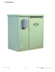
2. Installation 2.1 Concrete Pad Preparation Pads can either be poured on site, or precast by Alpha Technologies. The mounting holes on the bottom of the side car will fit both a standard PN-3 pad, and a CE3X pad. Precast pad model number PCD-SC-3X, Alpha P/N 641-064-10 is available for this system.
2. Installation 2.2 Utility Power Connection CAUTION: NOTE: The “Utility Power Connection” procedure must ONLY be performed by qualified service personnel and in compliance with local electrical codes and common safety practices. Connection to utility power must be approved by the local utility before installing the power supply. UL and NEC require that a service disconnect switch (UL listed) be provided by the installer and be connected between the power source and the ALPHA power supply.
2. Installation 2.2 Utility Power Connection, continued 240VAC Service (XM Series 2 915-240 Power Supply; XM Series 2 92248 for UPE-4 and UPE-8): Enclosures used with the XM Series 2 915-240 or 922-48 are equipped with a 240VAC duplex receptacle to provide power to the power supply and peripheral equipment. The receptacle, NEMA 615R, is protected by a single, 2-pole, common trip 15 Amp circuit breaker located inside the service entrance.
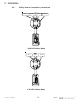
2. Installation 2.2 Utility Power Connection, continued Neutral Ground Line ON ISE 120 VAC 15 Amp OFF Neutral Ground Line ON ISE 120 VAC 20 Amp OFF Ground Line 2 Line 1 ON ISE 240 VAC 15 Amp OFF 031-099-C0-001 Rev.
2. Installation 2.2 Utility Power Connection, continued From Utility Ground 120 VAC Entrance OFF © 2000 TM Line 2 Service Neutral ON Service Ground 240 VAC Entrance Line 1 From Utility ON ON OFF OFF To Enclosure Line 1 Neutral To Enclosure 9 031-099-C1-001 Rev.
2. Installation 2.2 Utility Power Connection, continued line 1 Neutral Line 2 Ground ON 2 0 OFF 240 VAC Meter Base line 1 Neutral Ground ON OFF 120 VAC Meter Base 031-099-C0-001 Rev.
2. Installation 2.3 Generator / Sidecar Inter-connecting Cables The following cables must be routed either through a 3" sweep or coupling: #4 AWG DC Output from the generator 120 VAC power from the CESC sidecar service entrance ECM or ACU Interface cable Sidecar Enclosure Back Wall Generator Enclosure Side Wall 3" PVC Coupling ECM Interface © 2000 TM 11 Line Neutral Ground 120 VAC From Service Entrance Positive Negative DC Output From Generator 031-099-C1-001 Rev.
2. Installation 2.4 Internal Components A cooling fan is required any time a Power Supply is housed in the side car. The fan is thermostatically controlled to turn on at 140 deg F and off at 110 deg F. The fan cable has a 'T' connector that attaches to the Power Supply output connection. Replace fuse only with a 1/4” X 1-1/4”, 5 Amp, 250 Volt (Alpha P/N 460-025-10). The Sidecar enclosure contains an Input Power Panel (IPP), one or two Service Power Inserters (SPI),and the Enclosure Grounding Rail.
2. Installation 2.5 Battery Pack Wiring 1 2 Upper Shelf 4 3 Lower Sheff 48 Volt Battery Pack © 2000 TM 1 3 2 36 Volt Battery Pack 13 031-099-C1-001 Rev.
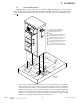
2. Installation 2.6 Power Supply Placement 1. Place the XM2 power supply onto the top shelf of the side car. 2. Verify that the AC Input Breaker in the service entrance is in the OFF position. 3. Verify that the Battery Breaker on the front of the power supply is in the OFF position. 4. Plug the AC power cord into the Input Power Panel on the side of the enclosure. 5. Plug the Battery Input Cable from the battery pack into the Battery Input connection on the front of the power supply. 6.
2. Installation 2.7 Battery Remote Temperature Sensor (RTS) Tools Needed: Adhesive Tape Procedure: For enclosures with multiple battery strings, the RTS must be located with the WARMEST battery string. This ensures proper operation of the battery charger’s temperature compensation circuit. Failure to locate the RTS with the warmest battery string could result in overcharging and premature battery failure. In this application, the RTS MUST be attached to a battery in the upper tray of the side-car.
2. Installation 2.8 Service Power Inserter 1. The SPI box(es) are mounted on the shelf support bracket. 2. Remove the two screws on the face of the SPI and lift off the cover to gain access to the Seizure Screw Assembly. Loosen the Seizure Screw several turns so that the stinger will pass through the clamp. (Fig 2-3) 3, Insert the Coaxial Termination into the output port on the bottom of the SPI. Ensure that the stinger goes through the Seizure Screw Assembly. Tighten the Coaxial Termination. 4.
© 2002 Investigate the of Alpha @ www.alpha.com ® UNITED STATES ASIA PACIFIC LATIN AMERICA Alpha Technologies 3767 Alpha Way Bellingham, WA 98226 Tel: (360) 647-2360 Fax: (360) 671-4936 Web: www.alpha.com CANADA Alpha Technologies 4084 McConnell Ct. Burnaby, B.C.