Operator’s Manual Alpha CFR 600, CFR 600XT and CFR 1000 UNINTERRUPTIBLE FROM ALPHA POWER SUPPLIES TECHNOLOGIES ALPHA TECHNOLOGIES
Operator’s Manual Alpha CFR 600, CFR 600XT and CFR 1000 UNINTERRUPTIBLE ©1995 Alpha Technologies POWER SUPPLIES 017-100-B0-001 7/95
IMPORTANT SAFETY INSTRUCTIONS CONTAINED IN THIS MANUAL CAUTION RISK OF ELECTRICAL SHOCK CAUTION: TO REDUCE THE RISK OF ELECTRICAL SHOCK, AND TO ENSURE THE SAFE OPERATION OF THIS UNIT, THE FOLLOWING SYMBOLS HAVE BEEN PLACED THROUGHOUT THE MANUAL. WHERE THESE SYMBOLS APPEAR, SERVICING SHOULD BE PERFORMED ONLY BY QUALIFIED PERSONNEL. DANGEROUS VOLTAGE A DANGEROUS VOLTAGE EXISTS IN THIS AREA. USE EXTREME CAUTION ATTENTION IMPORTANT OPERATING INSTRUCTIONS. FOLLOW THESE INSTRUCTIONS CLOSELY.
THE ALPHA CFR IMPORTANT SAFETY PRECAUTIONS CAREFULLY UNPACK THE CFR. REPORT ANY SHIPPING DAMAGE IMMEDIATELY. PLEASE READ THE OPERATORS MANUAL. IF YOU HAVE QUESTIONS REGARDING THE SAFE INSTALLATION OF THE CFR, CONTACT ALPHA TECHNOLOGIES. RETURN THE ENCLOSED WARRANTY CARD. THIS WILL ALLOW US TO SERVE YOU BETTER. THE UPS SHOULD BE SERVICED ONLY BY QUALIFIED PERSONNEL. WHEN NOT IN SERVICE, THE UPS BATTERIES SHOULD BE CHARGED AT LEAST ONCE EVERY THREE MONTHS TO ENSURE OPTIMUM PERFORMANCE AND BATTERY LIFE.
The Alpha CFR Table of Contents THE ALPHA CFR 600 and CFR 1000 UNINTERRUPTIBLE POWER SUPPLY 1. INTRODUCTION 1.1 The Alpha CFR 1.2 The CFR Advantage 1.3 Unpacking and Inspection 1 1 2 4 2. FEATURES 2.1 A Tour of the CFR 2.2 CFR Front Panel 2.3 CFR Rear Panel 2.4 Information Management Options 5 5 5 6 8 Standard Interface Device Intelligent Interface Device External Modem 2.
The Alpha CFR Table of Contents, continued 4. OPERATION, continued 4.2 Using the Standard Interface Device 22 UPS Powering Up Output Shutdown Pending Output Shutdown in Progress Line Present Operation Line Failure (AC Input Out of Tolerance) Line Failure Operation Line Synchronization Low Battery Warning Low Battery Shutdown Test Service Alarm Off Switch Manual Start / (Hold to Test) Switch Output Load Display 5. RS-232 TERMINAL COMMUNICATIONS 5.1 Remote RS-232 Operation 5.
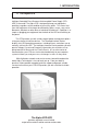
1. INTRODUCTION 1.1 The Alpha CFR Congratulations on your purchase of one of the most advanced and intelligent Controlled Ferro Resonant-Uninterruptible Power Supply (CFRUPS) in the world! The Alpha CFR is designed to keep your equipment operating, regardless of the condition of your utility power. This means that your vital equipment will no longer be affected by spikes, surges, sags, noise, brownouts, blackouts or other forms of electrical disturbances.
1. INTRODUCTION 1.2 The CFR Advantage ADVANCED POWER PROTECTION TECHNOLOGY Power protection devices can be judged by the type and quality of power they provide. Alpha CFR Uninterruptible Power Supplies provide continuous, conditioned “computer-grade” AC power to electronic equipment such as Computer Systems, Point of Sale Terminals, Process Controls, Telecommunications, CATV Headend, Broadband LAN, Manufacturing Control Systems, Critical Care and Hospital Lab Equipment.
1. INTRODUCTION 1.2 The CFR Advantage, continued COMMUNICATIONS AND INTELLIGENCE Alpha's interchangeable Standard Interface Device and Intelligent Interface Device allows your CFR to become an active part of your communications network providing you with a variety of interface options. SELF-TEST CAPABILITIES The CFR has a built-in, self-test function that checks all critical areas of the UPS, including the batteries, to ensure optimum performance.
1. INTRODUCTION 1.3 Unpacking and Inspection Carefully remove the UPS from its shipping container. Inspect the contents. If items appear to be damaged or missing, contact Alpha Technologies and the shipping company immediately. Most shipping companies have only a short claim period. Make sure the following items have been included: 1. CFR Series UPS with AC Line Cord 2. Operator's Manual 3. Any other ordered options SAVE THE ORIGINAL SHIPPING CONTAINER.
2. FEATURES 2.1 A Tour of the CFR The Alpha CFR is designed to be easy to use and extremely flexible. The CFR’s interchangeable front panel interface devices provide you with a wide range of information management options. The rear panel accepts a variety of connectors and receptacle plates to facilitate your most demanding communication and powering needs. 2.
2. FEATURES 2.3 CFR Rear Panel AC INPUT Connector The UPS is equipped with a standard, grounded AC power cord. EXTERNAL BATTERY Connector The connector accepts a standard plug from the EBP Series Battery Pack. Extending backup time is as simple as plugging in the battery pack. BATTERY Circuit Breaker The battery breaker protects the DC circuit.
2. FEATURES 2.3 CFR Rear Panel Exhaust Fan The UPS contains a rear panel exhaust fan to ensure maximum cooling protection during all modes of operation. OUTPUT Receptacle Plate The load (equipment to be protected) connects to the rear panel output receptacles. Styles vary depending upon country, frequency and voltage.
2. FEATURES 2.4 Information Management Options Standard Interface Device The Standard Interface Device provides you with vital UPS operating parameters from front panel LED's (see section 4.2). The Standard Interface also has a load indicator to help you determine precise loading on your UPS, plus Manual Start and Alarm Off switches. To ensure optimum backup performance, the Standard Interface comes with a self-test feature which lights the “Service” LED whenever a problem is detected.
2. FEATURES 2.4 Information Management Options, continued Intelligent Interface Device (optional) The Intelligent Interface Device (I2D) option is available either as a replacement of the Standard Interface Device (SID) or as a desktop unit for remotely accessing the unit (up to 2000 ft.). The desktop unit comes with an optional modem for accessing the UPS information via a telephone line.
2. FEATURES 2.5 Communication / Interface Options The CFR is equipped with four rear panel jacks for communication and remote interfaces: RS-232 Serial data; LAN Interface; External I 2D and External Alarms. NOTE: With the SID installed in the UPS, either the External I2D port or the RS-232 port can be activated. The factory default is set for RS-232 operation. With the internal I2D option installed in the UPS both ports are active.
2. FEATURES 2.5 Communication / Interface Options, continued Rear Panel Connectors: Below are the various communication connectors as they appear on the back of the CFR-UPS. The photographs show the pin numbering for the different connector types.
2. FEATURES 2.5 Communication / Interface Options RS-232 Connector: The connection/specifications for the RS-232 serial port vary depending on the installed interface device (i.e., SID or I 2D option). RS-232 connections for the standard CFR-UPS (with SID display or internal I2D) The standard CFR-UPS configuration with SID or internal I2D connects to a computer or terminal using a standard straight-through RS232 cable.
2. FEATURES 2.5 Communication / Interface Options, continued LAN Interface Connector The Alpha UPS provides a LAN interface port on a DE-9 female connector. This port may be used to monitor the status of the UPS and shutdown the output using basic UPS monitoring and shutdown software. Two dry contacts are provided to indicate LINE FAIL and LOW BATTERY status information. The port also accepts a dry contact input or an RS-232 level input to shutdown the UPS output.
2. FEATURES 2.5 Communication / Interface Options External I2D Connector The external I2D connector provides an interface for the optional desktop Intelligent Interface Device (I2D). This allows the CFR to be remotely monitored and controlled from up to 2,000 feet away.
2. FEATURES 2.5 Communication / Interface Options, continued External Alarms Connector, continued Pin out: (RJ-45 connector, centered key) Pin 1 Line Present Line Failure Pin out: (RJ-45 connector, Female) N.C. 1. 2. 3. 4. 5. 6. 7. 8. N.C. Low Battery Warning LINE FAIL, COM contact LINE FAIL, N. C. contact LINE FAIL, N. O. contact LOW BATTERY, N. O. contacts LOW BATTERY, COM contacts LOW BATTERY, N. C. contacts Battery OK N.C. = Normally Closed N.O. = Normally Open N.O.
3. INSTALLATION 3.1 Pre-Installation DO NOT CONNECT THE UPS TO A LINE CONDITIONER, ISOLATION TRANSFORMER OR ANY OTHER SIMILAR TYPE OF DEVICE. DAMAGE TO THE UPS AND THE LINE CONDITIONING EQUIPMENT CAN OCCUR. Site Preparation The UPS should be installed upright in a well-ventilated, dust free environment. The weight of the UPS, especially if it has an optional battery pack, is quite heavy (see specifications). Do not place the unit on any surface unable to fully support its weight.
3. INSTALLATION 3.2 Connecting the CFR 1. Connect the CFR's AC power cord to the wall receptacle. 2. If using an external battery pack, plug its connector into the rear panel of the UPS (see section 3.3). 3. Start and test the UPS without the load connected (see section 4.1). After testing, switch the unit OFF before connecting the load. 4. Plug the equipment to be protected into the UPS rear panel receptacles. Note: The load should be switched OFF prior to connection. 5.
3. INSTALLATION 3.3 External Battery Pack The CFR is designed so that battery backup time can be greatly extended simply by plugging the EBP 24 External Battery Pack into the back of the UPS. Battery packs are completely self-contained. Unit EBP 24A EBP 24C EBP 24E Rating 17 Ah 66 Ah 176 Ah Voltage Run Time* CFR 600 0.66 hrs 3.75 hrs 8.5 hrs 24 VDC 24 VDC 24 VDC CFR 600XT 1 hrs 4.3 hrs 9.0 hrs CFR 1000 0.5 hrs 2.1 hrs 5.
4. OPERATION 4.1 Start-up and Test 1. Plug the CFR’s AC line cord into a wall receptacle. The TEST LED and OUTPUT LOAD display LEDs will flash for a few seconds to indicate the CFR is powering up. The LINE PRESENT LED will then come ON to indicate the AC input line is OK and the CFR is running on AC line power. 2. Switch the rear panel BATTERY circuit breaker ON to activate the battery circuit. 3. Test the UPS by unplugging the AC LINE cord from the wall receptacle.
4. OPERATION 4.1 Start-up and Test, continued Switching OFF the UPS: 1. Switch all equipment connected to the UPS OFF. 2. Switch the rear panel “BATTERY” circuit breaker OFF. This will prevent the UPS from initiating LINE FAILURE operation when AC power is removed. 3. Unplug the CFR's AC power cord from the wall receptacle.
4. OPERATION 4.2 Using the Standard Interface Device The Standard Interface Device displays vital UPS operating parameters and has the ability to self-test the UPS at the touch of a button. When used in conjunction with the CFR's rear-panel “Form-C” contact closures, UPS status information can be sent directly to a Local Area Network (see section 2.5).
4. OPERATION 4.2 Using the Standard Interface Device UPS Powering Up Whenever the CFR is powering up, the TEST LED flashes for a few seconds. At the same time the OUTPUT LOAD indicator LEDs flash in a chasing pattern to indicate that there is no output. As soon as the power up sequence is completed, the TEST LED switches OFF and the OUTPUT LOAD display LEDs show the percentage of the load. Output Shutdown Pending The TEST LED will flash to indicate that a UPS output shutdown is pending to occur.
4. OPERATION 4.2 Using the Standard Interface Device Line Present Operation The green “LINE PRESENT” LED indicates that the UPS is running on AC line (utility / mains) power. Line Failure (AC Input Out of Tolerance) Whenever AC line voltage becomes unacceptably high or low (+10 % / -25%), or the line frequency exceeds + 3%, the "LINE PRESENT" LED flashes and the "LINE FAILURE" LED lights indicating the UPS is running on backup power. NOTE: High generator THD can also cause this condition.
4. OPERATION 4.2 Using the Standard Interface Device, continued Low Battery Warning The red “LOW BATTERY WARNING” LED precedes “LOW BATTERY SHUTDOWN” by 2 to 5 minutes and indicates that the batteries can no longer support the load. Immediate steps should be taken to begin an orderly system shutdown. From LOW BATTERY WARNING, it may take several hours to fully recharge the batteries.
4. OPERATION 4.2 Using the Standard Interface Device, continued Alarm Off Switch The switch cancels the audible LOW BATTERY WARNING alarm. The alarm remains disabled until line power is restored and the batteries are recharged. ALARM OFF Switch Manual Start / (Hold to Test) Switch The switch is used to start the UPS from battery power whenever AC line power is not available (“LINE PRESENT” LED OFF).
5. RS-232 TERMINAL COMMUNICATION 5.1 Remote RS-232 Operation Introduction: This section of the manual describes how to monitor, control and calibrate the CFR-UPS using RS-232 ASCII commands and how to navigate through the program using the menu structure. The RS-232 serial interface is designed to work with terminal emulation software in an interactive mode. Various parameters and commands may be accessed either through the menus or by typing the number associated with the desired functions. See section 5.
5. RS-232 TERMINAL COMMUNICATION 5.2 RS-232 Menu Selection Icons Icons have been placed throughout this section to easily guide you to key commands using remote terminal emulation. The icons provide short cuts to desired display screens without having to step through various menus. To use the icons, simply enter the number contained in the icon screen while you are in the terminal emulation mode. A dark screen icon with white numbers accesses one of the 7 main menus.
5. RS-232 TERMINAL COMMUNICATION 5.3 Remote Terminal Quick Reference The menu items outlined in this manual can be accessed from a remote terminal. The numbers contained in this guide act as a quick reference to accessing menu functions. Single-digit numbers relate to specific main menus. Double-digit numbers relate to specific sub-menus.
5. RS-232 TERMINAL COMMUNICATION 5.4 Menu Commands Overview Overview: The following section provide a general overview of the menu structure and give some examples of how to perform certain command functions such as testing the UPS. Querying CFR Status and Measured Parameters The current status (mode of operation) of the CFR and all active alarms are displayed at the end of the opening menu (see section 5.12 for a list of status messages and alarm events). Press “ENTER” to query CFR status and alarms.
5. RS-232 TERMINAL COMMUNICATION 5.4 Menu Commands Overview, continued Calibrating the CFR The CFR-UPS may be calibrated using two sets of parameters Maintenance Parameters (commands “70” to “79”) and Service Parameters (commands “80” to “89”). Maintenance parameters allow you to customize the CFR detection and warning levels. There should be no need to change these setting unless wider or narrower detection tolerances are required.
5. RS-232 TERMINAL COMMUNICATION 5.5 System Parameters The “SYSTEM PARAMETERS” screen provides UPS battery temperature information and manual initiation and termination of SELF TEST. 1 Battery Temperature Displayed in degrees C, Ambient Temperature is measured inside the UPS in the vicinity of the battery compartment. 11 Start Test Self Test can be initiated by selecting this menu. The test duration default is 60 seconds.
5. RS-232 TERMINAL COMMUNICATION 5.6 Input Parameters 2 “INPUT PARAMETERS” provides UPS Input Voltage, Current, Volt Amps, Power in Watts, Power Factor, and Line Frequency information. Voltage The voltage measured at the input of the UPS (i.e., 120 VAC). Current The flow of current measured at the input of the UPS (i.e., 3.1 Amps). Volt Amps The apparent input power of the UPS calculated by multiplying input voltage by the input current (i.e., 663 VA).
5. RS-232 TERMINAL COMMUNICATION 5.7 Output Parameters 3 “OUTPUT PARAMETERS” provides UPS Output Voltage, Current, Volt Amps, Power in Watts, Power Factor, and Line Frequency information. OUTPUT #1 Voltage The RMS voltage measured at the output of the UPS (i.e., 120 VAC). Current The flow of current measured at the output of the UPS (i.e., 3.1 Amps). OUTPUT #2 Voltage Not available on this unit and should read ‘0’. Current Not available on this unit and should read ‘0’.
5. RS-232 TERMINAL COMMUNICATION 5.8 Battery Parameters 4 “BATTERY PARAMETERS” provides UPS Battery Voltage, Charger Current, and Charger Status information. Voltage Voltage indicates the average DC voltage of UPS batteries. When the UPS is running in “LINE PRESENT” mode and the batteries are charged, the voltage will be approximately 27.6 VDC (equal to the charger’s “FLOAT” charge).
5. RS-232 TERMINAL COMMUNICATION 5.9 User Parameters 5 “USER PARAMETERS” allows you to set the information for automatic test, output voltage shutdown, display unit identification, and to change the security codes. Whenever one of the USER PARAMETER items is accessed, you are prompted for a security code. Note: The code (1111) is preset at the factory and can be changed by entering the SET USER SECURITY CODE screen (menu item 58).
5. RS-232 TERMINAL COMMUNICATION 5.9 User Parameters, continued Set Test Schedule The UPS can be setup to perform a routine self-test at intervals you specify. This will place the UPS into “LINE FAILURE” mode at a specific time in order to test its functionality and the capacity of the batteries. 53 Set Test Start (DD:HH:MM = dd:hh:mm) dd = Days hh = Hours mm = Minutes (i.e., “05:02:15” represents start test in 5 days, 2 hours, 15 minutes).
5. RS-232 TERMINAL COMMUNICATION 5.9 User Parameters, continued 58 Set User Security Code The security code is used to restrict entry into certain areas of the program. The code (1111) is preset at the factory and allows access to USER PARAMETERS and HISTORY programs. The security code can be changed using the number keys on the keypad. CAUTION: If the security code is changed and no record is kept, especially if the code becomes forgotten or lost, you will not be able to reenter the program.
5. RS-232 TERMINAL COMMUNICATION 5.9 User Parameters, continued 503 504 Cancel Output Shutdown This command cancels any pending or current UPS output shutdown. This command requires the USER SECURITY CODE. Recover Output Shutdown Only When AC Line Restored (xxx) xxx=“Yes” or “No”, (Default value is “Yes”) This command determines when the CFR restores output power after a output shutdown. If this option is set to “Yes”, the UPS restores output when the input AC line is restored.
5. RS-232 TERMINAL COMMUNICATION 5.9 User Parameters, continued 509 Disable Transmission of Unsolicited Alarms “509 None (xxxx)”; xxxx= “active” or blank; default is “active.” Setting this option to “active” disables the transmission of all unsolicited alarm messages. USER SECURITY CODE is required to set this option.
5. RS-232 TERMINAL COMMUNICATION 5.10 Maintenance Parameters 7 “MAINTENANCE PARAMETERS” allow you to customize UPS detection and warning characteristics. Normally, there should be no need to change these factory settings. CAUTION: If any of these parameters are changed, it is vital to thoroughly test the UPS since an improper adjustment can render the unit useless.
5. RS-232 TERMINAL COMMUNICATION 5.10 Maintenance Parameters 78 79 Max. PLL Slew Rate Increasing this value will reduce the speed at which the Phase Locked Loop (PLL) will change the output frequency while the UPS resumes LINE PRESENT operation after a line fault has been corrected. It will also increase the time required to resume LINE PRESENT operation.
5. RS-232 TERMINAL COMMUNICATION 5.11 Parameter Dump Command (Function 0) 0 Parameter Dump Command (Function 0) Function ‘0’ displays all UPS parameters in the following format: #####,###.#,#####,#####,##.##,###.#,#####,###.#,#####,###.#,#####,#####,##.##, ###.#,###.#,###.#,xxxxx,#####,#####,#####,#,##,##,##,##,##,##,##,##, ###############,############ Where ‘#’ indicates a digit or a blank character and ‘x’ represents a letter. The string is terminated by a Carriage Return and a Line Feed.
5. RS-232 TERMINAL COMMUNICATION 5.12 Event Descriptions (Alarms) There are 6 alarm groups which upon activation will be displayed at the end of the opening menu.
5. RS-232 TERMINAL COMMUNICATION 5.12 Event Descriptions (Alarms), continued Several alarms can be triggered during the same event. If there is a loss of AC line voltage, for example, the UPS may detect a glitch, low frequency and blackout. Low Battery Warning (LO_BAT_WARN) - The batteries are near the end of their useful charge. If AC line power is not restored within a short period of time, output power will be lost. All systems should be shutdown immediately to prevent loss of data.
5. RS-232 TERMINAL COMMUNICATION 5.12 Event Descriptions, continued Blackout (BLACKOUT) - The blackout alarm is triggered when the input voltage is lost for 12 ms, or when the RMS input voltage is less than 1/2 the nominal voltage for 100 ms or longer. * * Frequency High (FREQ_HI) - A frequency high alarm is triggered when there is a power line problem where the input frequency increases beyond the preset limit.
5. RS-232 TERMINAL COMMUNICATION 5.12 Event Descriptions, continued Input Line Fail - Indicates that the UPS switched to backup power to protect the equipment for one (or more) of the above conditions. * * Normal Line Mode - Indicates that the UPS is drawing power from the AC line and charging the batteries. Test Mode - Indicates the UPS was put into a test mode condition either by the TEST SCHEDULE routine or by pressing the TEST button on the Intelligent Interface Device's panel.
5. RS-232 TERMINAL COMMUNICATION 5.
6. MAINTENANCE 6.1 CFR Maintenance The electronic components used in the UPS require no maintenance. If the unit fails to perform a specific function, refer to the troubleshooting guide. The guide lists typical symptoms, causes and solutions that apply to the UPS, starting with the most obvious and working systematically through the unit.
6. MAINTENANCE 6.3 Battery Testing To determine the maximum amount of battery run time available, run this test at least once a year. The length of the test can vary from several minutes to many hours and should not be done during critical applications. Since the test discharges the batteries, backup power may not be readily available (for several hours) in the event of a utility power failure. 1. Unplug the AC Line cord from the wall receptacle. The front panel “LINE FAILURE” LED will come ON.
6. MAINTENANCE 6.4 Removing the CFR Front Panel and Cover CAUTION: INTERNAL MAINTENANCE SHOULD BE SERVICED ONLY BY QUALIFIED PERSONNEL. 1. 2. 3. 4. Disconnect all loads from the OUTPUT receptacles on the UPS. Switch the rear panel BATTERY circuit breaker OFF. Disconnect the UPS from the AC wall receptacle. If an external battery pack is connected to the UPS, remove the connector from the UPS rear panel. 5. Loosen the two (2) Phillips screws from the UPS front panel (located in the lower grill).
6. MAINTENANCE 6.5 Internal Battery Replacement Internal Battery Replacement (For CFR 600) IMPORTANT: READ THE SAFETY PRECAUTIONS LOCATED AT THE FRONT OF THE MANUAL BEFORE PROCEEDING. WARNING: DO NOT SHORT OUT BATTERY TERMINALS. (Note: All references to left and right are made facing the front of the CFR) 1. Switch OFF all power to the UPS and turn the battery breaker to the OFF position. 2. Remove the CFR front panel and cover. (Refer to section 6.4). 3.
6. MAINTENANCE 6.5 Internal Battery Replacement, continued Internal Battery Replacement (For CFR 600XT and CFR 1000) IMPORTANT: READ THE SAFETY PRECAUTIONS LOCATED AT THE FRONT OF THE MANUAL BEFORE PROCEEDING. GENERAL WARNING: DO NOT SHORT OUT BATTERY TERMINALS. (Note: All references to left and right are made facing the front of the CFR) 1. Switch OFF all power to the UPS and turn the battery breaker to the OFF position. 2. Remove the CFR front panel and cover. (Refer to section 6.4). 3.
6. MAINTENANCE 6.
6. MAINTENANCE 6.6 Troubleshooting Guide SYMPTOM No Output Power: "LINE PRESENT" OFF "LINE FAILURE" OFF CAUSE Utility power outage; or AC power cord unplugged; or AC input circuit breaker OFF. and BATTERY circuit breaker OFF. REMEDY Plug in AC power cord. Reset breaker. Reset breaker. Unit does not resume LINE PRESENT operation when power returns: "LINE PRESENT" ON (or flashing) "LINE FAILURE" ON AC line voltage too high or low; or UPS is in its synchronization mode. Wait for voltage to stabilize.
6. MAINTENANCE 6.6 Troubleshooting Guide, continued SYMPTOM CAUSE No output voltage during utility outage: "LINE PRESENT" OFF "LINE FAILURE" OFF "LOW BATTERY SHUTDOWN" ON Battery voltage below low voltage cutout (after long outage). or Battery voltage below low voltage cutout (after several short outages). Wait for line power to return and recharge batteries. BATTERY breaker tripped. or Loose battery cable or connection. or Faulty batteries. Reset breaker.
6. MAINTENANCE 6.7 Troubleshooting Using the SID The OUTPUT LOAD LED’s, located on the front panel of the Standard Interface Device, are designed to display UPS fault conditions once the unit has detected an internal problem, indicated by the SERVICE LED. This information provided by the LED’s is extremely useful during troubleshooting and maintenance. If the UPS is equipped with an I2D, refer to its operator’s manual for further troubleshooting information.
6. MAINTENANCE 6.7 Troubleshooting Using the SID, continued SYMPTOM CAUSE REMEDY Call Alpha. OVERLOAD LED (ON) SERVICE LED (ON) ALARM OFF switch pressed and held: Fast Detector / Low Sensitivity Fault. 100% LED (Flashing) SERVICE LED (ON) ALARM OFF switch pressed and held: Wait for line power to PLL Fault. return. Instability in line freq from generator; or out of Check wiring. phase wiring. 100% LED (ON) SERVICE LED (ON) ALARM OFF switch pressed and held: High Ambient Temp.
6. MAINTENANCE 6.8 Repair Instructions Before returning a unit to Alpha Technologies for repair, a Return Material Authorization (RMA) should first be obtained from Alpha's Customer Service Department. The RMA number should be clearly marked on the unit’s original shipping container. If the original container is no longer available, the UPS should be packed with at least 3 inches of shock-absorbent material. Note: Do not use popcorn-type packing material.
7. SPECIFICATIONS 7.1 Specifications Output Power (VA) Active Power (WATTS) Input Voltages @ 50 Hz (VAC) Input Current Max. (A) Input Voltages @ 60 Hz (VAC) Input Current Max. (A) CFR 600 600 400 230 2.5 120 4.8 CFR 600XT 600 400 230 2.5 120 4.8 CFR 1000 1000 750 230 4.3 120 8.3 Output Voltages @ 50 Hz (VAC) Output Current Max. (A) Output Voltages @ 60 Hz (VAC) Output Current Max. (A) 230 2.6 120 5.0 230 2.6 120 5.0 230 4.3 120 8.3 Efficiency @ Full Load (%) Efficiency @ .
7. SPECIFICATIONS 7.1 Specifications, continued Common Specifications Input Frequency Input Voltage Variation Output Frequency Output Regulation Total Harmonic Distortion Output Waveform Step Load Response Noise Attenuation Common Mode Normal Mode Low Voltage Trigger High Voltage Trigger Batteries Battery Voltage Batt. Low Volt. Cutout Charger Charger Voltage Operating Temp Heat Output Indicators Controls Connectors Output Alarms 600, [1000 ] 60 Hz or 50 Hz (± 3% Hz) - 25% to + 10% ± 0.
8. WARRANTY WARRANTY ALPHA TECHNOLOGIES Alpha Technologies warrants its equipment to be free of manufacturing defects in material and workmanship for a period of 24 months from the date of manufacture. The liability of Alpha Technologies under this warranty is solely limited to repairing, replacing, or issuing credit (at the discretion of Alpha Technologies) provided that: 1.
62
EMERGENCY SHUTDOWN EMERGENCY SHUTDOWN IMPORTANT THE UPS CONTAINS MORE THAN ONE LIVE CIRCUIT. DURING AN EMERGENCY, UTILITY POWER MAY BE DISCONNECTED AT THE SERVICE ENTRANCE OR MAIN ELECTRICAL PANEL TO PROTECT EMERGENCY PERSONNEL; HOWEVER, POWER WILL STILL BE PRESENT AT THE UPS OUTPUT. TO PREVENT THE POSSIBILITY OF INJURY TO SERVICE OR EMERGENCY PERSONNEL, ALWAYS SWITCH THE UPS REAR PANEL BATTERY CIRCUIT BREAKER(S) OFF TO DEENERGIZE THE CIRCUIT. EMERGENCY SHUTDOWN PROCEDURE: 1. 2.
ALPHA CANADA Alpha Technologies 5700 Sidley Street Burnaby, B.C. V5J 5E5 Tel: (604) 430-1476 FAX: (604) 430-8908 TECHNOLOGIES UNITED STATES Alpha Technologies 3767 Alpha Way Bellingham, WA 98226 Tel: (360) 647-2360 FAX: (360) 671-4936 UNITED KINGDOM Alpha Technologies Cartel Business Estate Edinburgh Way Harlow, Essex CM20 2DU Tel: +44-1279-422110 FAX: +44-21279-423355 GERMANY Alpha Technologies Hansastrasse 8 D-91126 Schwabach Tel: 49-9122-997303 FAX: 49-9122-997321 MIDDLE EAST Alphatec P.O.