Information Management Using the Intelligent Interface Device CANADA Alpha Technologies 5700 Sidley Street Burnaby, B.C. V5J 5E5 (604) 430-1476 FAX: (604) 430-8908 TECHNOLOGIES UNITED STATES Alpha Technologies 3767 Alpha Way Bellingham, WA 98226 (206) 647-2360 FAX: (206) 671-4936 ALPHA Operator's Manual TECHNOLOGIES ALPHA UNITED KINGDOM Alphatec U.K.
The Intelligent Interface Device Operator's Manual Information Management Using the Intelligent Interface Device ©1993 Alpha Technologies 018-029-B0 9/93
The Intelligent Interface Device Operator's Manual Information Management Using the Intelligent Interface Device ©1993 Alpha Technologies 018-029-B0 9/93
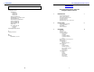
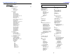
7. APPENDIX The Intelligent Interface Device Table of Contents 7.4 Index, continued U (continued) user parameters, 22 set parity, 24 modem, 24 RS-232, 24 RS-485, 25 set phone number, 25 set maintenance security code, 24 set test duration, 22 set test frequency D, W, M, 22 set test schedule, 22 set test start date, 22 set test start time, 22 set time, 22 set security code, 23 history, 23 user, 23 unpacking and inspection, iv Information Management Using the Intelligent Interface Device 1.
The Intelligent Interface Device 7. APPENDIX Table of Contents, continued 3. Index, continued OPERATION, continued 20 Battery Parameters Voltage Charger Current Charger Status User Parameters Set Time Set Date Set Test Schedule Set Test Start Time Set Test Start Date Set Test Frequency (D, W, M) Set Test Duration Battery AH Capacity Set Key Click Set User / History Security Code Display Unit Ident. Set Comm.
The Intelligent Interface Device 7.
1. INTRODUCTION 7. APPENDIX Unpacking and Inspection The Intelligent Interface Device, standard with the CFR 7.5K, CFR 10K, and CFR 15K, requires no installation. It is optional on all other CFR units and comes either factory installed or as a user-installable kit. Note: The Intelligent Interface Device is not user-installable on the CFR 600 or CFR 1000. If the unit is going to be used in a remote application, it simply plugs into the MMJ connector located on the back of all CFR units.
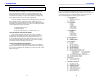
7. APPENDIX 1. INTRODUCTION Serial Operation Standards How To Use This Manual Parameter RS-232 RS-485 Mode of operation Single-ended Differential Number of drivers and receivers allowed 1 driver 1 receiver 32 drivers 32 receivers Maximum cable length (ft) 50 4000 Maximum data rate bits-per second 20K 10M Maximum common-mode voltage + 25 V 12 V / -7 V Driver output + 5 V min. + 15 V max. + 1.5 V min. Driver slew rate 30 V/u S max.
1. INTRODUCTION 7. APPENDIX Specifications The Intelligent Interface Device Alpha's Intelligent Interface Device provides precise UPS system information at the touch of a finger. The front panel keypad and LCD guide you through the various menu options which include Battery Temperature, Input Voltage and Current1, Line Frequency, Output Voltage and Current, Input and Output VA1, Power in Watts1, Power Factor, Battery Voltage and Charger Current, Charger Status, and more.
1. INTRODUCTION 6. MAINTENANCE Repair Instructions Front Panel Indicators Before returning a unit to Alpha Technologies for repair, a Return Material Authorization (RMA) should first be obtained from Alpha's Customer Service Department. The RMA number should be clearly marked on the unit’s original shipping container. If the original container is no longer available, the unit should be packed with at least 3 inches of shock-absorbent material. Note: Do not use popcorn-type packing material.
1. INTRODUCTION 5. COMMUNICATION INTERFACE OPTIONS Front Panel Screens The LCD display used on the Intelligent Interface Device provides vital UPS status information. Screens are displayed, one at a time, by pressing the ARROW keys on the front panel keypad. Main screens (menus) are linearly sequenced (see next page), starting with the Alpha Technologies (TIME and DATE) default screen. Once the OPENING MENU is displayed, options within the screen allow you to select specific parameter screens.
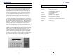
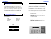
5. COMMUNICATION INTERFACE OPTIONS 1. INTRODUCTION Remote Communications Operation 1 53 1. You can directly access the Intelligent Interface Device by typing the number associated with the desired function on the PC keyboard and pressing ENTER (see illustration below). As an example, typing a "1" and pressing the ENTER key will display the SYSTEM PARAMETERS screen. The OPENING MENU command icons are displayed in the margins throughout the manual. 2.
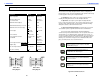
5. COMMUNICATION INTERFACE OPTIONS 1. INTRODUCTION Modem Installation (optional) Illuminated LCD TEST Key The Intelligent Interface Device can be equipped with an optional modem to provide long-range communications. Note: Installing the modem will disable the RS-485 port. MUTE Key To install the modem, you must first remove the CFR UPS's front panel (page 9) to access the Intelligent Interface Device.
1. INTRODUCTION 5. COMMUNICATION INTERFACE OPTIONS RS-485 Serial Operation Front Panel Features RS-485 is standard with the Intelligent Interface Device and will allow the UPS to be used in high speed, differential mode, multidrop communications applications. Connection is made to the PC terminal or LAN via either of the RJ-11 jacks located on the back of the UPS. To configure the UPS for RS-485 communication, refer to the SET RS485 PORT in Section 3 "User's Parameters".
1. INTRODUCTION 5. COMMUNICATION INTERFACE OPTIONS Front Panel Features, continued Illuminated Keys Illuminated keys are active and can be used for entering data or selection of menus, etc. Non-illuminated keys are not available for the selected function and are inactive. Pressing a non-illuminated key will have no effect. Initially, either before using the keypad or after 2 minutes of inactivity, the display will be dark and only the ENTER and CLEAR keys will be illuminated.
2. INSTALLATION 4. ALARMS Low Battery Warning UPS Front Panel Installation LOW BATTERY WARNING, indicated by the "LOW BATTERY" and "WARNING" displays, precedes LOW BATTERY SHUTDOWN. It indicates that the batteries are approaching full discharge and that the load can no longer be supported. Immediate steps should be taken to protect the load or begin a smooth shutdown of all loads connected to the UPS.
3. OPERATION 2. INSTALLATION UPS Front Panel Installation, continued Maintenance Parameters, continued 7. Take the existing Standard Interface Device out of the front panel by removing the board's four corner mounting screws. Unplug the LED board's ribbon cable from the micro board and set the assembly aside. 8. Install the Intelligent Interface Device through the front panel and, using the brass tab with the four screws (removed in step 7), secure the assembly to the front panel.
3. OPERATION 2. INSTALLATION Contrast Adjustment Maintenance Parameters "MAINTENANCE PARAMETERS" allow you to customize UPS detection and warning characteristics. Normally, there should be no need to change these factory settings. Once the correct security code has been entered, the fields can be altered by using the < arrow to decrease the setting, or the > arrow to increase the setting.
3. OPERATION 2. INSTALLATION Remote Installation Event Descriptions, continued The Intelligent Interface Device can also be used for remote applications away from the UPS. The distance is dependent upon the gauge of wire used: 300 feet with standard telephone line cord; 1,000 feet with 24 gauge cable; 2,000 feet with 22 gauge cable. The remote Intelligent Interface Device sits on a desktop and requires no additional retrofit. Simply plug its cable into the back of the UPS.
3. OPERATION 3. OPERATION Event Descriptions, continued Blackout - A blackout is a complete loss of AC Line power. * * Frequency High - A frequency high is a power line problem where the input frequency increases. * * Frequency Low - A frequency low is a power line problem where the input frequency decreases. * * Output Voltage Low - This is a warning that the output of the UPS is too heavily loaded. Reduce the load connected to the UPS.
3. OPERATION 3. OPERATION Event Descriptions There are a number of EVENTS that can be detected and recorded in the EVENT HISTORY log. Some of these conditions can be damaging to sensitive equipment, such as computers, resulting in data loss, system crashes, or equipment failure.
3. OPERATION 3. OPERATION History Logs 6 61 62 Front Panel Indicators "HISTORY LOGS" allow you to review and clear the EVENT HISTORY files. These files are useful in keeping accurate records of ALARM conditions and the number of times the UPS has supported AC LINE FAILURES. When the HISTORY LOGS screen is first accessed, (and before history files are cleared), you are prompted for a security code.
3. OPERATION 3. OPERATION Alpha Technologies (DEFAULT) Screen The "ALPHA TECHNOLOGIES" default screen displays date and time information. The default screen is continually displayed until another screen is selected from the front panel keypad. Whenever a screen is left idle for 2 minutes, the unit will return to the default screen. Note: The display will also go into a "sleep" mode (extinguishing the backlighting on the LCD and keypad to conserve energy) whenever it is left idle for 2 minutes or more.
3. OPERATION 3. OPERATION User Parameters, continued 59 Set Maintenance Security Code The Maintenance Security Code is a second level of security and is used to gain access to the maintenance programs. The code can be changed using the number keys on the keypad. CAUTION: If the code is changed and no record is kept, especially if the code becomes forgotten or lost, you will not be able to re-enter the program. The factory default setting is 1111.
3. OPERATION 3. OPERATION Input Parameters 2 User Parameters, continued "INPUT PARAMETERS" provides UPS Input Voltage, Current, Volt Amps, Power in Watts, Power Factor, and Line Frequency information. The main menu prompts you to select any of the six options by pressing the > arrow to advance through the various parameter screens; or < to step back through the screens. Press ENTER when the correct screen appears. 57 Voltage The voltage measured at the input of the UPS (i.e., 208 VAC).
3. OPERATION 3. OPERATION User Parameters 5 51 52 Output Parameters "USER PARAMETERS" allows you to set the UPS time and date, enter the capacity of the batteries used in the UPS, and to change the security codes. When the USER PARAMETER screen is first accessed, you are prompted for a security code. Note: The code (1111) is pre-set at the factory and can be changed by entering the SET SECURITY CODE screen.
3. OPERATION 3. OPERATION Battery Parameters 4 "BATTERY PARAMETERS" provides UPS Battery Voltage, Charger Current, and Charger Status information. The main menu prompts you to select any of the options by pressing the > arrow to advance through the various parameter screens; or < to step back through the screens. Press ENTER when the correct screen appears. Voltage When the UPS is running in "LINE PRESENT" mode, the charger voltage is displayed (i.e., 27.4 VDC for 24 volt systems; 54.
3. OPERATION 3. OPERATION Battery Parameters 4 "BATTERY PARAMETERS" provides UPS Battery Voltage, Charger Current, and Charger Status information. The main menu prompts you to select any of the options by pressing the > arrow to advance through the various parameter screens; or < to step back through the screens. Press ENTER when the correct screen appears. Voltage When the UPS is running in "LINE PRESENT" mode, the charger voltage is displayed (i.e., 27.4 VDC for 24 volt systems; 54.
3. OPERATION 3. OPERATION User Parameters 5 51 52 Output Parameters "USER PARAMETERS" allows you to set the UPS time and date, enter the capacity of the batteries used in the UPS, and to change the security codes. When the USER PARAMETER screen is first accessed, you are prompted for a security code. Note: The code (1111) is pre-set at the factory and can be changed by entering the SET SECURITY CODE screen.
3. OPERATION 3. OPERATION Input Parameters 2 User Parameters, continued "INPUT PARAMETERS" provides UPS Input Voltage, Current, Volt Amps, Power in Watts, Power Factor, and Line Frequency information. The main menu prompts you to select any of the six options by pressing the > arrow to advance through the various parameter screens; or < to step back through the screens. Press ENTER when the correct screen appears. 57 Voltage The voltage measured at the input of the UPS (i.e., 208 VAC).
3. OPERATION 3. OPERATION User Parameters, continued 59 Set Maintenance Security Code The Maintenance Security Code is a second level of security and is used to gain access to the maintenance programs. The code can be changed using the number keys on the keypad. CAUTION: If the code is changed and no record is kept, especially if the code becomes forgotten or lost, you will not be able to re-enter the program. The factory default setting is 1111.
3. OPERATION 3. OPERATION Alpha Technologies (DEFAULT) Screen The "ALPHA TECHNOLOGIES" default screen displays date and time information. The default screen is continually displayed until another screen is selected from the front panel keypad. Whenever a screen is left idle for 2 minutes, the unit will return to the default screen. Note: The display will also go into a "sleep" mode (extinguishing the backlighting on the LCD and keypad to conserve energy) whenever it is left idle for 2 minutes or more.
3. OPERATION 3. OPERATION History Logs 6 61 62 Front Panel Indicators "HISTORY LOGS" allow you to review and clear the EVENT HISTORY files. These files are useful in keeping accurate records of ALARM conditions and the number of times the UPS has supported AC LINE FAILURES. When the HISTORY LOGS screen is first accessed, (and before history files are cleared), you are prompted for a security code.
3. OPERATION 3. OPERATION Event Descriptions There are a number of EVENTS that can be detected and recorded in the EVENT HISTORY log. Some of these conditions can be damaging to sensitive equipment, such as computers, resulting in data loss, system crashes, or equipment failure.
3. OPERATION 3. OPERATION Event Descriptions, continued Blackout - A blackout is a complete loss of AC Line power. * * Frequency High - A frequency high is a power line problem where the input frequency increases. * * Frequency Low - A frequency low is a power line problem where the input frequency decreases. * * Output Voltage Low - This is a warning that the output of the UPS is too heavily loaded. Reduce the load connected to the UPS.
3. OPERATION 2. INSTALLATION Remote Installation Event Descriptions, continued The Intelligent Interface Device can also be used for remote applications away from the UPS. The distance is dependent upon the gauge of wire used: 300 feet with standard telephone line cord; 1,000 feet with 24 gauge cable; 2,000 feet with 22 gauge cable. The remote Intelligent Interface Device sits on a desktop and requires no additional retrofit. Simply plug its cable into the back of the UPS.
3. OPERATION 2. INSTALLATION Contrast Adjustment Maintenance Parameters "MAINTENANCE PARAMETERS" allow you to customize UPS detection and warning characteristics. Normally, there should be no need to change these factory settings. Once the correct security code has been entered, the fields can be altered by using the < arrow to decrease the setting, or the > arrow to increase the setting.
3. OPERATION 2. INSTALLATION UPS Front Panel Installation, continued Maintenance Parameters, continued 7. Take the existing Standard Interface Device out of the front panel by removing the board's four corner mounting screws. Unplug the LED board's ribbon cable from the micro board and set the assembly aside. 8. Install the Intelligent Interface Device through the front panel and, using the brass tab with the four screws (removed in step 7), secure the assembly to the front panel.
2. INSTALLATION 4. ALARMS Low Battery Warning UPS Front Panel Installation LOW BATTERY WARNING, indicated by the "LOW BATTERY" and "WARNING" displays, precedes LOW BATTERY SHUTDOWN. It indicates that the batteries are approaching full discharge and that the load can no longer be supported. Immediate steps should be taken to protect the load or begin a smooth shutdown of all loads connected to the UPS.
1. INTRODUCTION 5. COMMUNICATION INTERFACE OPTIONS Front Panel Features, continued Illuminated Keys Illuminated keys are active and can be used for entering data or selection of menus, etc. Non-illuminated keys are not available for the selected function and are inactive. Pressing a non-illuminated key will have no effect. Initially, either before using the keypad or after 2 minutes of inactivity, the display will be dark and only the ENTER and CLEAR keys will be illuminated.
1. INTRODUCTION 5. COMMUNICATION INTERFACE OPTIONS RS-485 Serial Operation Front Panel Features RS-485 is standard with the Intelligent Interface Device and will allow the UPS to be used in high speed, differential mode, multidrop communications applications. Connection is made to the PC terminal or LAN via either of the RJ-11 jacks located on the back of the UPS. To configure the UPS for RS-485 communication, refer to the SET RS485 PORT in Section 3 "User's Parameters".
5. COMMUNICATION INTERFACE OPTIONS 1. INTRODUCTION Modem Installation (optional) Illuminated LCD TEST Key The Intelligent Interface Device can be equipped with an optional modem to provide long-range communications. Note: Installing the modem will disable the RS-485 port. MUTE Key To install the modem, you must first remove the CFR UPS's front panel (page 9) to access the Intelligent Interface Device.
5. COMMUNICATION INTERFACE OPTIONS 1. INTRODUCTION Remote Communications Operation 1 53 1. You can directly access the Intelligent Interface Device by typing the number associated with the desired function on the PC keyboard and pressing ENTER (see illustration below). As an example, typing a "1" and pressing the ENTER key will display the SYSTEM PARAMETERS screen. The OPENING MENU command icons are displayed in the margins throughout the manual. 2.
1. INTRODUCTION 5. COMMUNICATION INTERFACE OPTIONS Front Panel Screens The LCD display used on the Intelligent Interface Device provides vital UPS status information. Screens are displayed, one at a time, by pressing the ARROW keys on the front panel keypad. Main screens (menus) are linearly sequenced (see next page), starting with the Alpha Technologies (TIME and DATE) default screen. Once the OPENING MENU is displayed, options within the screen allow you to select specific parameter screens.
1. INTRODUCTION 6. MAINTENANCE Repair Instructions Front Panel Indicators Before returning a unit to Alpha Technologies for repair, a Return Material Authorization (RMA) should first be obtained from Alpha's Customer Service Department. The RMA number should be clearly marked on the unit’s original shipping container. If the original container is no longer available, the unit should be packed with at least 3 inches of shock-absorbent material. Note: Do not use popcorn-type packing material.
1. INTRODUCTION 7. APPENDIX Specifications The Intelligent Interface Device Alpha's Intelligent Interface Device provides precise UPS system information at the touch of a finger. The front panel keypad and LCD guide you through the various menu options which include Battery Temperature, Input Voltage and Current1, Line Frequency, Output Voltage and Current, Input and Output VA1, Power in Watts1, Power Factor, Battery Voltage and Charger Current, Charger Status, and more.
7. APPENDIX 1. INTRODUCTION Serial Operation Standards How To Use This Manual Parameter RS-232 RS-485 Mode of operation Single-ended Differential Number of drivers and receivers allowed 1 driver 1 receiver 32 drivers 32 receivers Maximum cable length (ft) 50 4000 Maximum data rate bits-per second 20K 10M Maximum common-mode voltage + 25 V 12 V / -7 V Driver output + 5 V min. + 15 V max. + 1.5 V min. Driver slew rate 30 V/u S max.
1. INTRODUCTION 7. APPENDIX Unpacking and Inspection The Intelligent Interface Device, standard with the CFR 7.5K, CFR 10K, and CFR 15K, requires no installation. It is optional on all other CFR units and comes either factory installed or as a user-installable kit. Note: The Intelligent Interface Device is not user-installable on the CFR 600 or CFR 1000. If the unit is going to be used in a remote application, it simply plugs into the MMJ connector located on the back of all CFR units.
The Intelligent Interface Device 7.
The Intelligent Interface Device 7. APPENDIX Table of Contents, continued 3. Index, continued OPERATION, continued 20 Battery Parameters Voltage Charger Current Charger Status User Parameters Set Time Set Date Set Test Schedule Set Test Start Time Set Test Start Date Set Test Frequency (D, W, M) Set Test Duration Battery AH Capacity Set Key Click Set User / History Security Code Display Unit Ident. Set Comm.
7. APPENDIX The Intelligent Interface Device Table of Contents 7.4 Index, continued U (continued) user parameters, 22 set parity, 24 modem, 24 RS-232, 24 RS-485, 25 set phone number, 25 set maintenance security code, 24 set test duration, 22 set test frequency D, W, M, 22 set test schedule, 22 set test start date, 22 set test start time, 22 set time, 22 set security code, 23 history, 23 user, 23 unpacking and inspection, iv Information Management Using the Intelligent Interface Device 1.
The Intelligent Interface Device COMPLETE THE FOLLOWING FOR YOUR RECORDS: 7. APPENDIX Addendum Interface ID # Software Version Options (i.e.
The Intelligent Interface Device COMPLETE THE FOLLOWING FOR YOUR RECORDS: 7. APPENDIX Addendum Interface ID # Software Version Options (i.e.
USA, LATIN AMERICA & ASIA PACIFIC Alpha Technologies 3767 Alpha Way Bellingham, WA 98226 Tel: (360) 647-2360 Fax: (360) 671-4936 Novus P1250 and 1250T CANADA Alpha Technologies 7033 Antrim Ave, Burnaby, BC, V5J 4M5 Tel: (604) 430-1476 Fax: (604) 430-8908 UNINTERRUPTIBLE POWER UNITED KINGDOM, EUROPE AND AFRICA FROM ALPHA SUPPLIES TECHNOLOGIES Alpha Technologies Cartel Business Estate Edinburgh Way Harlow, Essex CM20 2DU Tel: +44-1279-422110 Fax: +44-1279-423355 GERMANY Alpha Technologies Hansastras