
Manual


How To Use This Manual
The manual has been designed to introduce and familiarize you with the
various features of the Alpha Intelligent Interface Device. It will guide you
through all phases of the unit, from installation through operation, either locally
from the keypad or remotely via a computer terminal.
The Installation section contains easy step-by-step instructions for
installing the Intelligent Interface Device into an Alpha CFR UPS.
The Operation section guides you through the Intelligent Interface
Device's extensive menuing system. This section includes the basic setup
and gives a brief explanation of the selections that are available, including
what options activate, control and monitor the UPS.
The Remote Communication Interface section provides an overview
of the available options, along with detailed instructions and illustrations.
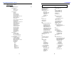
Icons have been placed throughout the manual to highlight key
commands using remote terminal emulation. The icons provide short cuts to
desired display screens without having to step through various menus. To
use the icons, simply enter the number contained in the icon screen while you
are in the terminal emulation mode. A dark screen icon with white numbers
will take you to a main menu. A light screen icon with black numbers will
place you directly into the chosen sub-menu function.
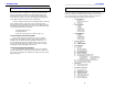
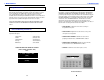
Typical PC Communication Icons
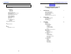
7. APPENDIX 1. INTRODUCTION
11
11
140
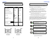
DCE to DE-9
Wiring Diagram
DCE to DB-25
Wiring Diagram
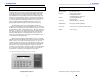
Serial Operation Standards
5
51
X
The dark screen icon with white lettering will take you
directly to a main menu. In this example, the #5 (USER
PARAMETERS) will appear.
The light screen icon with black lettering will take you
directly to a sub-menu. In this example, the #51 (USER
PARAMETERS-SET TIME) will appear.
This function is not independently selectable as a sub-menu
item. It is included as part of the USER PARAMETERS
main screen selection.
This function cannot be set, (or accessed), via terminal
emulation. You must use the keypad on the Intelligent
Interface Device.
Parameter RS-232 RS-485
Mode of operation Single-ended Differential
Number of drivers and 1 driver 32 drivers
receivers allowed 1 receiver 32 receivers
Maximum cable length (ft) 50 4000
Maximum data rate bits-per second 20K 10M
Maximum common-mode voltage + 25 V 12 V / -7 V
Driver output + 5 V min. + 1.5 V min.
+ 15 V max.
Driver slew rate 30 V/u S max. NA
Driver output short circuit / 500 mA to VCC 150 mA to
current limit or GND GND
250 mA to
-8 V or 12 V
Driver output resistance Power-ON NA 120K ohms
(High Z state) Power-OFF 300 ohms 120K ohms
Receiver input resistance 3K - 7K ohms 12K ohms
Receiver sensitivity + 3 V + 200 mV