Cordex 125-4.
This page intentionally left blank. Argus Technologies Ltd. Burnaby, British Columbia. Telephone: 604 436 5900 Fax: 604 436 1233 Argus Technologies reserves the right to make changes to the products and information contained in this document without notice. Copyright 2008 Argus Technologies Ltd. Argus® is a registered trademark of Argus Technologies Ltd. All Rights Reserved. Printed in Canada. Visit www.argus.
Cordex 125-4.4kW Modular Switched Mode Rectifier 010-589-B2 The following documents and drawings are included in this manual to provide the necessary information required for installation, operation and fault diagnosis of the unit: • Specifications, Cordex 125-4.
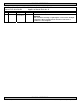
MANUAL ADDENDUM Unit Description: Cordex 125-4.4kW Modular Switched Mode Rectifier Manual P/N: 010-589-B2 Applies to Manual Revision: A # 1 Date 07-11-20 Page# 7 of 010-589-C0 Line# 37 Correction to be implemented Add text to Section 5.5: WARNING Use care when removing or replacing the covers for the AC input connections. Never assume that an electrical connection or conductor is not energized. MANUAL ADDENDUM Authorized by: FORM 954-010-10 010589b2a1_addendum_coverplates.
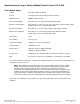
Specifications for Argus’ Switched Mode Rectifier Cordex 125-4.4kW Power Module Output Voltage: 90 to 160Vdc within rated limits Current: 35.2A @ 125Vdc nominal (40A @ 110Vdc maximum) Maximum Power: 4400W continuous/module Static Load Regulation: Better than ±0.5% for any load change within rated limits Dynamic Load Regulation: Better than ±5% for 40% - 90 - 40% step load change at nominal output voltage (output shall recover to static limits within 30ms) Static Line Regulation: Better than ±0.
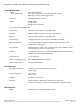
Specifications for Argus’ Switched Mode Rectifier Cordex 125-4.4kW Continued Power Module Input Voltage: Extended Operation: 208 to 240Vac nominal Low: 187 to 90Vac (power de-rated linearly to 40% output) High: 265 to 312Vac (de-rated power factor) Frequency: 50/60Hz nominal (45 to 70Hz) Current: 20A @ 240Vac 23A @ 208Vac 26A @ 187Vac (maximum) Recommended Feeder Breaker: 30A Power Factor: >0.
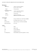
Specifications for Argus’ Switched Mode Rectifier Cordex 125-4.4kW Continued Mechanical Module Dimensions: Weight: 19” Shelf (fits 5 modules) Dimensions: 160mm H x 87mm W x 300mm D [6.3" H x 3.4" W x 11.8" D] 4.65 kg (10.25 lb.) 177mm H x 442mm W x 389mm D [7" H x 17.4" W x 15.3" D] Weight: 8.5 kg (18.7 lb.
Specifications for Argus’ Switched Mode Rectifier Cordex 125-4.
WARRANTY AND REPAIR INFORMATION Warranty Policy Argus Technologies Ltd. warrants all equipment manufactured by it to be free from defects in parts and labor, excluding third party OEM materials (example: air conditioners, batteries), for a period of two years from the date of shipment from the factory. For third party products the OEM’s warranty shall apply.
CSA/NRTL — MARKS — BACKGROUND What are the CSA and NRTL? CSA (Canadian Standards Association also known as CSA International) was established in 1919 as an independent testing laboratory in Canada. CSA received its recognition as an NRTL (Nationally Recognized Testing Laboratory) in 1992 from OSHA (Occupational Safety and Health Administration) in the United States of America (Docket No. NRTL-2-92). This was expanded and renewed in 1997, 1999, and 2001.
IMPORTANT SAFETY INSTRUCTIONS SAVE THESE INSTRUCTIONS 1. Please read this manual prior to use to become familiar with the product’s numerous features and operating procedures. To obtain a maximum degree of safety, follow the sequences as outlined. 2. This manual provides warnings and special notes for the user: a. Points that are vital to the proper operation of the product or the safety of the operator are indicated by the heading: WARNING. b.
This page intentionally left blank.
TABLE OF CONTENTS 1 INTRODUCTION ............................................................................................................................................................. 1 1.1 1.2 1.3 2 RECTIFIER FEATURES ................................................................................................................................................... 2 2.1 2.2 2.3 2.4 2.5 2.6 2.7 2.8 2.9 2.10 2.11 2.12 2.13 3 Safety Precautions ......................................................
8 MAINTENANCE ........................................................................................................................................................... 14 8.1 8.2 9 Fan Replacement........................................................................................................................................ 14 MOV Replacement......................................................................................................................................
1 Introduction 1.1 Scope of the Manual This instruction manual explains the installation, interconnection, and operation of Argus Technologies’ Cordex 125-4.4kW modular switched mode rectifiers. NOTE: To aid the user with installation, frequent reference is made to drawings located at the rear of the manual. 1.2 Product Overview A complete Cordex rectifier system consists of one or more power modules in a common shelf enclosure.
2 Rectifier Features 2.1 Front Panel LEDs Thumbscrew Figure 1–Cordex 125-4.4kW rectifier front panel 2.1.1 LEDs The front panel LEDs provide: • • • Rectifier status summary, Rectifier software upgrade in progress indication, Locate module pattern. Rectifier status summary will show the rectifier alarm status, communication fail status and rectifier on/off status. 2.1.1.1 AC ON The top LED (green) is on when AC is within valid range.
2.1.1.4 LED Activity During Software Upload When a rectifier software upload is in progress, the LEDs will behave in a distinctly different way to indicate new rectifier software is being transferred from the CXC. When a rectifier data transfer is in progress, all three LEDs will flash in a sequence lasting 1.5 seconds. When the last LED is lit, the sequence is repeated beginning at the first LED. 2.1.1.
2.6 Wide AC Range A minor alarm is generated when the AC input voltage drops below specification. Rectifier output power is reduced linearly between 187Vac and 90Vac to 40% of the rated output power (the unit will deliver derated output power down to 80Vac). At 80Vac, the module will shut down and will not restart until the AC is greater than or equal to 90Vac; however, the restart voltage depends on the load current. At reduced load current the unit may restart with the input voltage as low as 100Vac.
3 Inspection 3.1 Packing Materials All Argus products are shipped in rugged, double walled boxes and suspended via solid inserts to minimize shock that may occur during transportation. Packaging assemblies and methods are tested to International Safe Transit Association standards. Products are also packaged with Cortex. This plastic wrap contains a corrosive-inhibitor that protects the product from corrosion for up to two years. 3.1.1 Returns for Service Save the original shipping container.
4 Installation This chapter is provided for qualified personnel to install the product, which shall be mounted in a clean and dry environment. NOTE: To aid the user with installation, frequent reference is made to drawings located at the rear of the manual. 4.1 Safety Precautions WARNING Hazardous voltages are present at the input of power systems.
5 Wiring and Connections This chapter provides cabling details and notes on cable sizing for DC applications with respect to the Argus Cordex 125-4.4kW modular switched mode rectifier. 5.1 Safety Precautions WARNING Hazardous AC voltages may be present. Ensure power at the AC service panel is off before attempting work on the AC connections. Use a voltmeter to verify the absence of voltage. Clearly mark the correct polarity of the battery leads before commencing work on DC connections.
5.6 Calculating Output Wire Size Requirements Wire size is calculated by first determining the appropriate maximum voltage drop requirement. Using the formula below calculate the CMA wire size requirement. Determine the size and number of conductors required to satisfy the CMA requirement. CMA = (A x LF x K) / AVD, where: CMA = Cross section of wire in circular MIL area A = Ultimate drain in amps LF = Conductor loop feet K = 11.
5.8 CAN Serial Ports Two CAN Serial ports (modular jacks with offset latches), are provided for communications with Argus’ Cordex rectifiers and other CAN-enabled equipment. These are located on the left side of the shelf (as viewed from the front). Daisy-chain from shelf to shelf (CAN OUT of one shelf to CAN IN of another) as necessary and ensure that only the last shelf is terminated. See Figure 2. 5.8.
6 Operation 6.1 Main Rectifier States Rectifier operation can be broken up into five main states: 1. 2. 3. 4. 5. Off, Start delay, Soft start, Normal operation, Turning off. Each state is characterized as being distinct and necessary for the operation of the rectifier. These states are briefly described below. 6.1.1 Off State The rectifier will be in the Off state immediately after power is applied to the rectifier or after a rectifier shutdown.
6.2 Main Rectifier Modes In addition to Main Rectifier States, there is a set of Main Rectifier Modes. These modes can be divided into two categories as follows: 6.2.1 Output Voltage Modes Voltage modes can be thought of as modes that, under software control, can directly adjust the output voltage.
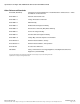
6.4 Factory Ranges and Defaults The following tables lists the rectifier settings/ranges/defaults; changes are made via the CXC: Setting Range (minimum to maximum) Default Float (FL) Voltage 90 – 160V 130.5V Equalize (EQ) Voltage 90 – 160V 132.9V Battery Test (BT) Voltage 90 – 160V 106.3V OVP See note below – 160V 137.
7 System Startup After completing the shelf wiring and installation, perform the following startup and test procedure to ensure proper operation: 7.1 Check System Connections • • 7.2 Verify AC and Power the Shelf • • • • 7.3 Install one power module. Verify AC input voltage is correct and turn on the corresponding AC input feeder breaker. The power module OK LED should illuminate after a preset start delay. Using the CXC, test functionality of various module alarms and controls.
8 Maintenance Although very little maintenance is required with Argus systems, routine checks and adjustments are recommended to ensure optimum system performance. Qualified service personnel should do repairs. The following table lists a few maintenance procedures for this system. These procedures should be performed at least once a year. WARNING: HIGH VOLTAGE AND SHOCK HAZARD. Use extreme care when working inside the shelf while the system is energized. Do not make contact with live components or parts.
1. 2. 3. 4. 5. 6. 7. 8. 8.2 Shut off the unit and unscrew the front fastener that secures the power module to the shelf. Slide the module 10 cm (4”) out of the shelf and wait two minutes for module capacitors to discharge. Remove the four screws (two each side) that secure the front panel to the module chassis. Slide the front panel out. Disconnect the fan power lead wires (one set per fan) and front panel ribbon cable from the module. Remove the screws that secure the fans to the front panel.
9 Argus Conventions 9.1 Numbering System Argus Technologies uses an eight-digit drawing number system, which is broken into three blocks. The first three digits describe the category of the product; e.g., rectifier or fuse panel. The next three digits indicate the sequence in which the product number was allocated in a particular category.
REVISIONS DESCRIPTION REV BY ADDED MOUNTING BRACKETS DATE APPD S.D.W. 0 5.92 150.3 5.42 137.6 7.42 188.4 6.92 175.7 10.36 263.1 9.86 250.4 11.86 301.2 11.36 288.5 16.10 408.9 15.28 388.2 B 17.40 441.9 0 17.40 441.9 LTR 6.97 6.55 6.05 5.05 177.0 166.4 153.7 128.3 0 REAR VIEW REAR COVER AND MODULES ARE HIDDEN (LIST 82 OUTPUT BARS) 0 0.93 23.6 TOP VIEW REAR COVER IS HIDDEN (LIST 82 OUTPUT BARS) 17.17 436.0 LIST 90 MODULE BLANK 010-589-20 4.
17.08 433.9 5.03 127.7 5.03 127.7 0 0 TOP VIEW LIST 19 - 19" MID-MOUNT TOP VIEW LIST 23 - 23" MID-MOUNT LIST 90 MODULE BLANK 010-589-20 4.4kW CORDEX MODULE 6.97 177.0 6.97 177.0 6.74 171.1 5.49 139.3 5.49 139.3 3.74 94.9 3.24 82.2 1.49 37.7 0.65 16.6 0 1.49 37.7 0.24 6.0 0 17.40 441.9 17.40 441.9 18.31 465.1 22.31 566.7 19.0 483 23.06 585.7 THESE DESIGNS AND SPECIFICATIONS ARE THE PROPERTY OF ARGUS TECHNOLOGIES AND SHALL NOT BE COPIED OR USED FOR MANUFACTURING WITHOUT ITS WRITTEN CONSENT.
REVISIONS LTR B REV BY DESCRIPTION ADDED MOUNTING BRACKETS DATE APPD S.D.W. SWITCH SETTING FOR CAN TERMINATION CAN UNTERMINATED CAN TERMINATED REMOVE COVERS AC WIREWAY BLANK PLATE J8 J7 REAR VIEWS AC WIREWAY (2 PLACES) 1.3 [34] HOLE FOR CUSTOMER SUPPLIED 1" CONDUIT FITTING SEE AC INPUT DETAILS PROTECTIVE EARTH TERMINAL 2 PLACES AC INPUT DETAILS SINGLE PHASE INPUTS, 208V - 277VAC L1 L2 L1 L2 CAN OUT RJ12 OFFSET PIN OUT (J8) 1. 2. 3. 4. 5. 6.
3/8" FLAT WASHER 3/8" LOCK WASHER 3/8-20 NUT POSITIVE (+) OUTPUT TERMINAL 3/8" FLAT WASHER 3/8" LOCK WASHER 3/8-20 NUT POSITIVE (+) OUTPUT TERMINAL DC WIRING (CUSTOMER SUPPLIED) POSITIVE (+) BUS BAR (CUSTOMER SUPPLIED) 3/8" FLAT WASHER 3/8-20 x 1" HEX BOLT NEGATIVE (-) OUTPUT TERMINAL NEGATIVE (-) OUTPUT TERMINAL 3/8" 2 HOLE COMPRESSION TERMINAL 1" SPACING (CUSTOMER SUPPLIED) 3/8" FLAT WASHER 3/8-20 x 1" HEX BOLT NEGATIVE (-) BUS BAR (CUSTOMER SUPPLIED) LIST 89 - REAR COVER REAR VIEW - DC CABLE INS
ARGUS TECHNOLOGIES SPARE PARTS LIST POWER MODULE, CORDEX 125-4.4KW DRAWING #010-589-G0 Type WD APPROVED: ______________ ISSUED: ______________ ITEM QTY PART NO. REV DESCRIPTION CIRCUIT DESIGNATION OR REMARKS List 0; ON SITE: 1 2 747-212-20 List 0 Assy,Fan,Cordex 24-3.1kW Fn100,101 2 1 707-374-20 List 0 Assy,PCB,Trans Protn,Cordex 3.
FACTORY SERVICE INFORMATION Technical Support Technical support staff are available for answering general questions related to installation, operation and maintenance of Argus products. In Canada and the USA, call Argus toll free 7:30 am to 5:00 pm Pacific Standard Time at: +1-888 GO ARGUS (+1-888-462-7487) For emergencies, call +1-888-GO-ARGUS 24 hours a day, seven days a week. Customers outside Canada and the USA, call +1-604-436-5547 for technical support.