Cordex Controller Panel Mount/Rack Mount 125/220Vdc 018-570-B2
This page intentionally left blank. Argus Technologies Ltd. Burnaby, British Columbia. Telephone: 604 436 5900 Fax: 604 436 1233 Argus Technologies reserves the right to make changes to the products and information contained in this document without notice. Copyright 2008 Argus Technologies Ltd. Argus® is a registered trademark of Argus Technologies Ltd. All Rights Reserved. Printed in Canada. Visit www.argus.
Cordex Controller Panel Mount/Rack Mount 125/220Vdc 018-570-B2 The following documents and drawings are included in this manual to provide the necessary information required for routine installation of the unit: • Specifications: 018-570-B1 • CSA/NRTL Equivalence: 048-554-10 • Important Safety Instructions and Installation: 018-570-C0 • Outline Drawings: 018-570-06 • Customer Connections: 018-570-08 • Warranty and Service Information: 048-700-10 • Service Centers: 048-693-10 Argus Technologies
This page intentionally left blank.
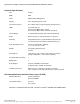
Specifications for Argus’ Cordex Controller Panel/Rack Mount 125/220Vdc Basic Unit Input Voltage: 90 to 300Vdc within rated limits MTBF: 472,000 @ 25°C (77°F) EMC: The unit meets requirements of: ICES-003 Class A EN 55022 Class A (CISPR 22) EN 61000-4-2 ESD EN 61000-4-3 Radiated Immunity EN 61000-4-4 EFT /Burst EN 61000-4-6 Conducted Immunity FCC Part 15 Class A, FCC Part 68 Ground Fault Detection: 0 – 10mA In accordance with FCC requirements, we provide the following statement as specified in the F
Specifications for Argus’ Cordex Controller Panel/Rack Mount 125/220Vdc Continued Hardware Specifications CPU: Coldfire RAM: 8MB Flash: 4MB standard, 4MB optional Display: 160 x 160 pixel grayscale LCD Front Panel Controls: Reset button and touch panel (display and input device) LED’s: System OK (Green) Power System Minor Alarm (Yellow) Power System Major Alarm / Controller Fail (Red) Internal Battery: 3V Lithium CR1616 [Argus part number #185-005-10] Audio: Built-in speaker for alarm and po
Specifications for Argus’ Cordex Controller Panel/Rack Mount 125/220Vdc Continued Part Numbers and List Options This product is available to order under the following part numbers and list options: Description Part Number/List Option Cordex Controller .......................................................................................................................................018-570-20 Basic unit.......................................................................................................
CSA/NRTL — MARKS — BACKGROUND What are the CSA and NRTL? CSA (Canadian Standards Association also known as CSA International) was established in 1919 as an independent testing laboratory in Canada. CSA received its recognition as an NRTL (Nationally Recognized Testing Laboratory) in 1992 from OSHA (Occupational Safety and Health Administration) in the United States of America (Docket No. NRTL-2-92). This was expanded and renewed in 1997, 1999, and 2001.
IMPORTANT SAFETY INSTRUCTIONS SAVE THESE INSTRUCTIONS 1. Please read this manual prior to use to become familiar with the product’s numerous features and operating procedures. To obtain a maximum degree of safety, follow the sequences as outlined. 2. This manual provides warnings and special notes for the user: a. Points that are vital to the proper operation of the product or the safety of the operator are indicated by the heading: WARNING. b.
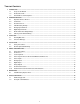
TABLE OF CONTENTS 1 INTRODUCTION ............................................................................................................................................................. 1 1.1 1.2 1.3 2 HARDWARE FEATURES ................................................................................................................................................. 2 2.1 2.2 2.3 2.4 2.5 2.6 2.7 2.8 3 Safety Precautions .................................................................................
1 Introduction 1.1 Scope of the Manual This instruction manual explains the installation and interconnection of the Cordex System Controller (CXC) 125/220Vdc panel (CXCP) and rack (CXCR) models from Argus Technologies. NOTE: To aid the user with installation, frequent reference is made to drawings located at the rear of this manual. 1.2 Product Overview The CXC 125/220Vdc is an advanced system controller designed by Argus for operation with 125/220Vdc power systems.
2 Hardware Features Behind the CXC’s front panel lies the main controller motherboard, which contains a microprocessor, memory, removable lithium battery, as well as numerous other electronic components. The input/output (I/O) board houses a series of terminal connections. Space is also available to add optional output relays or an internal modem. Connections are oriented for front access. 2.1 Operator Interface Devices The user interfaces with the CXC by one or more of the following methods: • • • 2.1.
Latch Touch Screen LEDs RS-232 (Craft Port) Reset Button Figure 3–Front view of Cordex controller panel model CXCP 2.1.6 Front Panel LEDs The CXC has three LEDs located on the front panel. These are used to display the alarm status of the power system, CXC progress and status during startup, file transfers and lamp tests. 2.1.6.1 Alarm Conditions The CXC illuminates the LED that corresponds to the system alarm status.
2.5 Analog Input Channels The CXCP and CXCR each have up to nine analog channels, including up to five voltage inputs, two current inputs, and two temperature inputs. 2.5.1 Voltage Inputs Voltage-input channel V2 provides monitoring of the charge (battery) voltage. The CXC software is pre-configured to monitor V2 for battery voltage. V2 is used as the system reference for rectifier float voltage, low voltage disconnect (LVD), system high voltage alarm, and system low voltage alarm. 2.5.
3 Inspection 3.1 Packing Materials All Argus products are shipped in rugged, double walled boxes and suspended via solid inserts to minimize shock that may occur during transportation. Packaging assemblies and methods are tested to International Safe Transit Association standards. Products are also packaged with Cortex. This plastic wrap contains a corrosive-inhibitor that protects the product from corrosion for up to two years. 3.1.1 Returns for Service Save the original shipping container.
4 Installation This chapter is provided for qualified personnel to install the product, which shall be mounted in a clean and dry environment. NOTE: To aid the user with installation, frequent reference is made to foldout drawings located at the rear of the manual. 4.1 Safety Precautions WARNING Hazardous voltages are present at both the input and the output of power systems.
5 Wiring and Connections This chapter provides cabling details and notes on cable sizing for DC applications with respect to the product. NOTE: Refer also to foldout drawings located at the rear of the manual. 5.1 Safety Precautions WARNING Hazardous voltages are present at both the input and the output of power systems. Ensure that input power and output power is removed before attempting work on the CXC’s connections. Use a voltmeter to verify the absence of voltage.
5.6 Analog Inputs WARNING Ensure the correct polarity is used for all input cable terminations. The analog input channels are used to monitor various types of electrical signals. Some of the analog channels are reserved for specific signals, while others are designated as general-purpose inputs, which accommodate various types of analog signals. Bundle the input cables together and route through the entry holes.
CAUTION: to reduce risk of fire, use only 0.129mm2 (#26 AWG) or larger wire.
5.8 Relay Outputs WARNING Relays are rated at 220Vdc 0.4A. Exceeding these limits may damage the relay and other circuitry in the CXC. Terminals 27 to 50 provide 8 Form C contacts (NO, COM and NC) for extending various alarm or control signals. Each relay output can be wired for NO and/or NC operation during an alarm or control condition. See Figure 6.
5.10 Network Connection and Remote Communications The Cordex system can be set up, monitored and tested via ETHERNET 10/100 Base-T or with a RS-232 serial data connection, or over a phone line using a modem. NOTE: Pinouts are shown in the customer connections drawing. The communication protocol supports a web interface. The remote screen display is an enhanced version of the CXC’s front panel display. Some standard scenarios are described below: 5.10.
See Figure 8 below for a rendering of CXC connections for power system communications: Technician's PC Standard Network Cable Intranet Internet Remote Monitor SNMP Server PSTN Modem Straight Through Cable Modem Rectifier Bus, RS-485 or CAN Expansion Bus System I/O or Ethernet RS-232 RS-485 CAN CAN Analog + Digital I/O Rectifiers Cordex Controller (CXC) RS-232 LCD Battery Cell Monitor Battery Cells Null Modem Cable Mains Monitor 3 Phase Mains Crossover Cable I/O Expansion Technician'
6 Maintenance Although very little maintenance is required with Argus systems, routine checks and adjustments are recommended to ensure optimum system performance. Qualified service personnel should do repairs. The following table lists a few maintenance procedures for this system. These procedures should be performed at least once a year. WARNING: HIGH VOLTAGE AND SHOCK HAZARD. Use extreme care when working inside the shelf while the system is energized. Do not make contact with live components or parts.
7 Argus Conventions 7.1 Numbering System Argus Technologies uses an eight-digit drawing number system, which is broken into three blocks. The first three digits describe the category of the product; e.g., rectifier or fuse panel. The next three digits indicate the sequence in which the product number was allocated in a particular category.
REVISIONS LTR DATE DESCRIPTION LTR APPD DESCRIPTION QTY FINISHED HOLE LEGEND THESE DESIGNS AND SPECIFICATIONS ARE THE PROPERTY OF ARGUS TECHNOLOGIES AND SHALL NOT BE COPIED OR USED FOR MANUFACTURING WITHOUT ITS WRITTEN CONSENT. DESIGN EOF 2003/06 DRAWN J.U. 2004/08 CHECKED MATERIAL ... ... FINISH APPROVED TOLERANCES X.X 0.04" X.XX 0.02" X.XXX 0.01" [X] [X.X] [X.XX] 1mm 0.5mm 0.25mm PER P.O. and Doc.
REVISIONS LTR DATE DESCRIPTION APPD TOP VIEW FRONT ISOMETRIC VIEW 37.5 1.48 171 6.73 175.3 6.90 175.3 6.90 155 6.10 131 5.16 LTR DESCRIPTION QTY FINISHED HOLE LEGEND THESE DESIGNS AND SPECIFICATIONS ARE THE PROPERTY OF ARGUS TECHNOLOGIES AND SHALL NOT BE COPIED OR USED FOR MANUFACTURING WITHOUT ITS WRITTEN CONSENT. 425.5 16.75 FRONT VIEW 8 .31 DESIGN EOF 2003/06 DRAWN J.U. 2004/08 CHECKED 99.1 3.90 ... ... FINISH APPROVED SIDE VIEW MATERIAL TOLERANCES X.X 0.04" X.XX 0.02" X.
REVISIONS LTR REV BY DATE DESCRIPTION APPD 482.7 19.00 465.1 18.31 425.5 16.75 22.2 .88 101.6 4.00 57.2 2.25 132.5 5.22 FRONT VIEW - 19" MOUNTING 584.3 23.00 566.7 22.31 425.5 16.75 22.2 .88 101.6 4.00 57.2 2.25 132.6 5.22 THESE DESIGNS AND SPECIFICATIONS ARE THE PROPERTY OF ARGUS TECHNOLOGIES AND SHALL NOT BE COPIED OR USED FOR MANUFACTURING WITHOUT ITS WRITTEN CONSENT. FRONT VIEW - 23" MOUNTING DESIGN EOF 2003/06 DRAWN J.U. 2004/08 MATERIAL ... ...
REVISIONS LTR DESCRIPTION DWN DATE CHKD APPD B UPDATED TO REV B PCB JU 2005/01 FL RD C UPDATED TO REV C PCB WH 2009/10 JK ME SUGGESTED WIRE ROUTING SYSTEM GROUND CONNECTION TIME CLOCK BACKUP BATTERY CR1616 ARGUS P/N 185-005-10 FRONT ISO VIEW COVER REMOVED PCB DETAIL OMITTED LIST 21 (19" RACK MOUNT OPEN POSITION SHOWN) SUGGESTED WIRE ROUTING THESE DESIGNS AND SPECIFICATIONS ARE THE PROPERTY OF ARGUS TECHNOLOGIES AND SHALL NOT BE COPIED OR USED FOR MANUFACTURING WITHOUT ITS WRITTEN CONSENT.
REVISIONS LTR 19 20 D1 21 22 D2 23 24 D3 25 26 D4 27 28 29 NC C NO 30 31 32 NC C NO 33 34 35 NC C NO 36 37 38 NC C NO 39 40 41 NC C NO 42 43 44 NC C NO 45 46 47 NC C NO 48 49 50 NC C NO 51 52 53 NC C NO RELAY #1 RELAY #2 RELAY #3 RELAY #4 RELAY #5 RELAY #6 RELAY #7 RELAY #8 RELAY #0 SYSTEM FAIL 54 55 +B PWR - DESCRIPTION REV BY DATE APPD 56 57 +A PWR - DETAIL A P3 6 3 4 5 7 8 9 10 GP1+ GP2+ GP3+ GP4+ GP2GP1GP3GP4- 1 2 V2+ V2- DCCT I1 11 12 T1+ T1- 13 14 15 16 T2+ T2- I2+ I
REVISIONS LTR RJ12 OFFSET RJ45 1 1 8 6 1. TX+ 2. TX3. RX+ 4. COM1 5. COM1 6. RX7. COM2 8. COM2 1. GND 2. CANH 3. CANL 4. CANL 5. CANH 6. NC ETHERNET CAN 1 CAN 2 RJ11 DESCRIPTION REV BY DATE APPD RJ12 OFFSET 1 4 1 6 J5 RS485 TELCO CAN2 J3 CAN1 J2 RS485 J8 J1 P1 To Front Panel J4 U1 MODEM 1. GND 2. RS485+ 3. RS4854. RS4855. RS485+ 6. SCI EN 1. NC 2. RING 3. TIP 4.
REVISIONS LTR DESCRIPTION REV BY DATE APPD SUGGESTED WIRE ROUTING DETAIL RIBBON CABLE NOT SHOWN C TOP VIEW-EXPANSION BOARD(707-179-20) LIST 96-EXPANSION BOARD, OUTPUT RELAY, 8 X 1A FORM C, INTERNAL 1 1 RELAY #10 RELAY #11 RELAY #12 RELAY #13 159 NC C7 N0 NC RELAY #14 RELAY #15 161 158 C6 N0 160 157 NC 156 C5 N0 155 153 NC 154 152 C4 N0 151 NC 150 144 RELAY #9 C3 N0 149 143 NC 148 142 C2 N0 147 141 NC 146 140 C1 N0 145 139 NC REAR VIEW DETAIL WITH EXPANSI
This page intentionally left blank.
WARRANTY AND SERVICE INFORMATION Technical Support Technical support staff are available for answering general questions related to installation, operation and maintenance of Argus products. In Canada and the USA, call Argus toll free at +1-888-GO-ARGUS (+1-888-462-7487) 7:30 am to 5:00 pm Pacific Standard Time. For emergencies, call +1-888-GO-ARGUS (+1-888-462-7487) 24 hours a day, seven days a week. Customers outside Canada and the USA, call +1-604-436-5547 for technical support.
Service Centers Factory Service Centers Canada and International Argus Technologies Ltd. ATTN: RMA Returns 7033 Antrim Avenue Burnaby, BC, V5J 4M5 Canada Tel: +1 604 436 5900 Fax: +1 604 436 1233 Email: returns@argusdcpower.com USA Argus Technologies Inc. ATTN: RMA Returns 3116 Mercer Avenue Bellingham, WA, 98225 USA Tel: +1-360 756 4904 Fax: +1-360 647 0498 Email: returns-usa@argusdcpower.com Asia-Pacific PCM Electronics (Dong Guan) Co., Ltd.