Cordex Controller Panel Mount/Rack Mount 018-587-B2 (018-557-20 pre-RoHS)
This page intentionally left blank. Argus Technologies Ltd. Burnaby, British Columbia. Telephone: 604 436 5900 Fax: 604 436 1233 Argus Technologies reserves the right to make changes to the products and information contained in this document without notice. Copyright 2008 Argus Technologies Ltd. Argus® is a registered trademark of Argus Technologies Ltd. All Rights Reserved. Printed in Canada. Visit www.argus.
Cordex Controller Panel Mount/Rack Mount 018-587-B2 (018-557-20 pre-RoHS) The following documents and drawings are included in this manual to provide the necessary information required for routine installation of the unit: • Specifications: 018-587-B1 • CSA/NRTL Equivalence: 048-554-10 • Important Safety Instructions and Installation: 018-587-C0 • Outline Drawing, CXCP, Panel Mount: 747-195-06 (RoHS: 747-474-20) • Outline Drawing, CXCR, Rack Mount: 747-198-06 (RoHS: 747-475-20) • Customer Connectio
This page intentionally left blank.
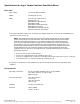
Specifications for Argus’ Cordex Controller Panel/Rack Mount Basic Unit Input Voltage: 17 to 65Vdc within rated limits MTBF: 472,000 @ 25°C (77°F) EMC: The unit meets requirements of: ICES-003 Class B EN 55022 Class B (CISPR 22) EN 61000-4-2 ESD EN 61000-4-3 Radiated Immunity EN 61000-4-4 EFT /Burst EN 61000-4-6 Conducted Immunity FCC Part 15 Class B, FCC Part 68 In accordance with FCC requirements, we provide the following statement as specified in the FCC guidelines for conformance to Part 15, Class
Specifications for Argus’ Cordex Controller Panel/Rack Mount Continued Hardware Specifications CPU: Coldfire RAM: 8MB Flash: 4MB standard, 4MB optional Display: 160 x 160 pixel grayscale LCD Front Panel Controls: Reset button and touch panel (display and input device) LED’s: System OK (Green) Power System Minor Alarm (Yellow) Power System Major Alarm / Controller Fail (Red) Internal Battery: 3V Lithium CR1616 [Argus part number #185-005-10] Audio: Built-in speaker for alarm and popup message
Specifications for Argus’ Cordex Controller Panel/Rack Mount Continued Part Numbers and List Options This product is available to order under the following part numbers and list options: Description Part Number/List Option Cordex Controller (Model: see Lists 80-82) [pre-RoHS #018-557-20] ....................................................018-587-20 Basic unit.....................................................................................................................................................
CSA/NRTL — MARKS — BACKGROUND What are the CSA and NRTL? CSA (Canadian Standards Association also known as CSA International) was established in 1919 as an independent testing laboratory in Canada. CSA received its recognition as an NRTL (Nationally Recognized Testing Laboratory) in 1992 from OSHA (Occupational Safety and Health Administration) in the United States of America (Docket No. NRTL-2-92). This was expanded and renewed in 1997, 1999, and 2001.
IMPORTANT SAFETY INSTRUCTIONS SAVE THESE INSTRUCTIONS 1. Please read this manual prior to use to become familiar with the product’s numerous features and operating procedures. To obtain a maximum degree of safety, follow the sequences as outlined. 2. This manual provides warnings and special notes for the user: a. Points that are vital to the proper operation of the product or the safety of the operator are indicated by the heading: WARNING. b.
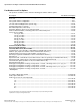
TABLE OF CONTENTS 1 INTRODUCTION ............................................................................................................................................................. 1 1.1 1.2 1.3 2 HARDWARE FEATURES ................................................................................................................................................. 2 2.1 2.2 2.3 2.4 2.5 2.6 2.7 2.8 3 Packing Materials...................................................................................
1 Introduction 1.1 Scope of the Manual This instruction manual explains the installation and interconnection of the Cordex System Controller (CXC) panel CXCP) and rack (CXCR) models from Argus Technologies. NOTE: To aid the user with installation, frequent reference is made to drawings located at the rear of this manual. The CXCM modular version of the controller plugs directly into the Cordex rectifier system shelf. The shelf manual provides CXCM installation details. 1.
2 Hardware Features Behind the CXC’s front panel lies the main controller motherboard, which contains a microprocessor, memory, removable lithium battery, as well as numerous other electronic components. The input/output (I/O) board houses a series of terminal connections. Space is also available (CXCP or CXCR only) to add optional output relays or an internal modem. Connections are oriented for front access. 2.
Latch Touch Screen LEDs RS-232 (Craft Port) Reset Button Figure 3–Front view of Cordex controller panel model CXCP, gray finish 2.1.6 Front Panel LEDs The CXC has three LEDs located on the front panel. These are used to display the alarm status of the power system, CXC progress and status during startup and file transfers. 2.1.6.1 Alarm Conditions The CXC illuminates the LED that corresponds to the system alarm status.
2.4 Lithium Battery Backup A removable lithium battery (see Specifications) is included in the system to retain time and date settings upon power loss or reset. 2.5 Analog Input Channels The CXC has up to ten analog channels, including up to five voltage inputs or up to four current inputs (see table in Customer Connections drawing at the rear of the manual). The remaining inputs may be configured (see List Options) for temperature and general purpose. 2.5.
3 Inspection 3.1 Packing Materials All Argus products are shipped in rugged, double walled boxes and suspended via solid inserts to minimize shock that may occur during transportation. Packaging assemblies and methods are tested to International Safe Transit Association standards. Products are also packaged with Cortex. This plastic wrap contains a corrosive-inhibitor that protects the product from corrosion for up to two years. 3.1.1 Returns for Service Save the original shipping container.
4 Installation This chapter is provided for qualified personnel to install the product, which shall be mounted in a clean and dry environment. NOTE: To aid the user with installation, frequent reference is made to foldout drawings located at the rear of the manual. 4.1 Safety Precautions WARNING Hazardous voltages are present at both the input and the output of power systems.
5 Wiring and Connections This chapter provides cabling details and notes on cable sizing for DC applications with respect to the product. NOTE: Refer also to foldout drawings located at the rear of the manual. 5.1 Safety Precautions WARNING Hazardous voltages are present at both the input and the output of power systems. Ensure that input power and output power is removed before attempting work on the CXC’s connections. Use a voltmeter to verify the absence of voltage.
5.3 Tools Required Various insulated tools are essential for product installation. Use this list as a guide: • • • • • • • • • 5.
5.6.2 Midpoint Monitoring (connection examples) An analog signal configured (at the factory) for voltage can be used for mid-point monitoring. Channel V1 is used in the examples below but any of the available 60V voltage channels can be used. NOTE: See CXC Software manual for detailed instruction on programming. Connect as shown ensuring correct polarity in each case: Figure 5–Connection examples for mid-point monitoring 5.
Terminal Description Signal Type Analog Inputs and System Signals 3 and 4; V2 Battery (Charge) Voltage Pos (+) / Neg (-) 13 and 14; I1 Load (Discharge) Current Pos (+) / Neg (-) 64, 65, and 66; DCCT DCCT Power Supply Pos (+) / Gnd / Neg (-) 67 and 68; B PWR Secondary Power Pos (+) / Neg (-) 69 and 70; A PWR Power Pos (+) / Neg (-) Digital Inputs – See Table A for definitions of logic and system 21 and 22; D1 Distribution Fuse/Circuit Breaker Pos (+) or Neg (-) 23 and 24; D2 Battery Fuse/Circuit Breaker Pos
NOTE: DCCT power supply (±15V) is provided only for analog input configurations with bi-voltage inputs; i.e. List 120 and List 125. DCCT power output is protected against short circuits and is able to power four DCCTs. CAUTION: to reduce risk of fire, use only #26 AWG (0.14mm²) or larger wire. NOTE: To aid the user with installation, frequent reference is made to drawings located at the rear of this manual. Custom configurations may be detailed within the Argus power system documentation package. 5.
5.9 Rectifier Connections 5.9.1 CAN Serial Port A single CAN serial port, for communications with Argus’ Cordex model rectifiers and other CAN-enabled equipment (nodes) on the same system, is located in between the Ethernet port and RS-485 port options. Daisy-chain from node to node (CAN OUT of one node to CAN IN of another) as necessary and ensure that only the last node is terminated. 5.
See Figure 9 below for a rendering of CXC connections for power system communications: Technician's PC Standard Network Cable Intranet Internet Remote Monitor SNMP Server PSTN Modem Straight Through Cable Modem [Communication Expansion Board] Rectifier Bus (RS-485 required for Argus Pathfinder rectifiers) System I/O or Ethernet RS-232 RS-485 CAN Analog + Digital I/O Rectifiers Cordex Controller (CXC) For Can Serial Port and Cordex Rectifiers: CAN Bus continued – last node must be terminated R
6 Sample System Drawings Figure 10–Sample system 1, CXCP with 2-tier Vista, LVD, temp comp, CSM11, and Cordex 24-3.1kW Argus Technologies Ltd. Printed in Canada. © 2008 Argus Technologies Ltd. ARGUS and CORDEX are trademarks of Argus Technologies Ltd. All Rights Reserved.
Figure 11–Sample system 2, CXC with LVD, BCM, and Cordex 48-3.6kW Argus Technologies Ltd. Printed in Canada. © 2008 Argus Technologies Ltd. ARGUS and CORDEX are trademarks of Argus Technologies Ltd. All Rights Reserved.
Figure 12–Sample system 3, CXC with Cordex Shunt Multiplexer, TPL fuses, and Cordex 48-3.6kW Argus Technologies Ltd. Printed in Canada. © 2008 Argus Technologies Ltd. ARGUS and CORDEX are trademarks of Argus Technologies Ltd. All Rights Reserved.
Figure 13–Sample system 4, CXCP with additional relays, 2-tier Vista, LVD, SD08, and Cordex 48-3.6kW Argus Technologies Ltd. Printed in Canada. © 2008 Argus Technologies Ltd. ARGUS and CORDEX are trademarks of Argus Technologies Ltd. All Rights Reserved.
7 Maintenance Although very little maintenance is required with Argus systems, routine checks and adjustments are recommended to ensure optimum system performance. Qualified service personnel should do repairs. The following table lists a few maintenance procedures for this system. These procedures should be performed at least once a year. WARNING: HIGH VOLTAGE AND SHOCK HAZARD. Use extreme care when working inside the shelf while the system is energized. Do not make contact with live components or parts.
8 Argus Conventions 8.1 Numbering System Argus Technologies uses an eight-digit drawing number system, which is broken into three blocks. The first three digits describe the category of the product; e.g., rectifier or fuse panel. The next three digits indicate the sequence in which the product number was allocated in a particular category.
REVISIONS LTR DESCRIPTION APPD DATE DESCRIPTION LTR QTY FINISHED HOLE LEGEND THESE DESIGNS AND SPECIFICATIONS ARE THE PROPERTY OF ARGUS TECHNOLOGIES AND SHALL NOT BE COPIED OR USED FOR MANUFACTURING WITHOUT ITS WRITTEN CONSENT. DESIGN EOF 2003/06 DRAWN EOF 2003/06 CHECKED REAR ISOMETRIC VIEW-OPENING DETAIL MATERIAL ... ... FINISH APPROVED PER P.O. and Doc. 070-024-83 TOLERANCES X.X X.XX X.XXX 0.04" 0.02" 0.01" [X] [X.X] [X.XX] 1mm 0.5mm 0.
REVISIONS LTR DESCRIPTION APPD DATE TOP VIEW FRONT ISOMETRIC VIEW 6.9 175.3 6.1 155 6.9 175.3 5.2 131 DESCRIPTION LTR QTY FINISHED HOLE LEGEND THESE DESIGNS AND SPECIFICATIONS ARE THE PROPERTY OF ARGUS TECHNOLOGIES AND SHALL NOT BE COPIED OR USED FOR MANUFACTURING WITHOUT ITS WRITTEN CONSENT. 16.8 425.5 FRONT VIEW 0.3 8 6.7 171 1.5 37.5 3.9 99.1 DESIGN EOF 2003/06 DRAWN EOF 2003/06 CHECKED ... ... FINISH APPROVED SIDE VIEW MATERIAL PER P.O. and Doc. 070-024-83 TOLERANCES X.
REVISIONS LTR DESCRIPTION APPD DATE ISOMETRIC VIEW LOCKED POSITION LEFT FRONT ISOMETRIC VIEW WITH COVER OFF 189.5 7.5 DESCRIPTION LTR QTY 131.5 5.2 FINISHED HOLE LEGEND THESE DESIGNS AND SPECIFICATIONS ARE THE PROPERTY OF ARGUS TECHNOLOGIES AND SHALL NOT BE COPIED OR USED FOR MANUFACTURING WITHOUT ITS WRITTEN CONSENT. DESIGN EOF 2003/06 DRAWN EOF 2003/06 CHECKED ... ... FINISH APPROVED ISOMETRIC VIEW OPEN POSITION MATERIAL PER P.O. and Doc.
REVISIONS LTR DESCRIPTION APPD DATE 425.5 16.8 ISOMETRIC VIEW 132.5 5.2 57.2 2.3 129.3 5.1 TOP VIEW DESCRIPTION LTR QTY FINISHED HOLE LEGEND 99.1 3.9 566.7 22.3 584.3 23.0 RIGHT VIEW THESE DESIGNS AND SPECIFICATIONS ARE THE PROPERTY OF ARGUS TECHNOLOGIES AND SHALL NOT BE COPIED OR USED FOR MANUFACTURING WITHOUT ITS WRITTEN CONSENT. DESIGN EOF 2003/06 DRAWN EOF 2003/06 CHECKED MATERIAL ... ... FINISH APPROVED PER P.O. and Doc. 070-024-83 TOLERANCES X.X X.XX X.XXX FRONT VIEW 0.
REVISIONS LTR DESCRIPTION APPD DATE 425.5 16.8 TOP VIEW 132.5 5.2 57.2 2.3 129.3 5.1 ISOMETRIC VIEW DESCRIPTION LTR QTY FINISHED HOLE LEGEND 99.1 3.9 465.1 18.3 THESE DESIGNS AND SPECIFICATIONS ARE THE PROPERTY OF ARGUS TECHNOLOGIES AND SHALL NOT BE COPIED OR USED FOR MANUFACTURING WITHOUT ITS WRITTEN CONSENT. RIGHT VIEW DESIGN EOF 2003/06 DRAWN EOF 2003/06 CHECKED 482.7 19.0 FRONT VIEW MATERIAL ... ... FINISH APPROVED PER P.O. and Doc. 070-024-83 TOLERANCES X.X X.XX X.XXX 0.
REVISIONS LTR DATE APPD B ADDED LIST OPTION:120,124,125 DESCRIPTION 2004/01 RD C CHANGED DESCRIPTIONS FOR GP3 2004/06 AND GP4 - SEE SHEET 2 OF 4 SUGGESTED WIRE ROUTING SYSTEM GROUND CONNECTION TIME CLOCK BACKUP BATTERY CR1616 ARGUS P/N 185-005-10 FRONT ISO VIEW COVER REMOVED PCB DETAIL OMITTED 747-198-20 (19" RACK MOUNT OPEN POSITION SHOWN) SUGGESTED WIRE ROUTING THESE DESIGNS AND SPECIFICATIONS ARE THE PROPERTY OF ARGUS TECHNOLOGIES AND SHALL NOT BE COPIED OR USED FOR MANUFACTURING WITHOUT
REVISIONS LTR TB21 TB20 TB19 TB18 TB22 TB23 D2 D3 D4 D5 D6 D1 21 22 23 24 25 26 27 28 29 30 31 32 TB24 D7 33 34 TB25 TB15 D8 35 36 TB11 NC K1C NO 37 38 39 TB12 NC K2C NO NC K3C NO 40 41 42 43 44 45 TB8 TB13 NC K4C NO NC K5C NO 46 47 48 49 50 51 TB16 TB14 NC K6C NO NC K7C NO 52 53 54 55 56 57 TB10 TB17 NC K8C NO NC K0C NO 61 62 63 58 59 60 REV BY DESCRIPTION TB7 TB30 +15V GRND -15V DCCT DCCT 64 65 66 + 67 B PWR 68 DATE APPD TB29 + 69 A PWR 70 DETAIL B NTS TB3 V1+ V11 2
REVISIONS LTR REV BY DESCRIPTION DATE APPD SUGGESTED WIRE ROUTING DETAIL RIBBON CABLE NOT SHOWN C TOP VIEW-EXPANSION BOARD(707-179-20) LIST 96-EXPANSION BOARD, OUTPUT RELAY, 8 X 1A FORM C, INTERNAL 1 1 TB6 TB7 REAR VIEW DETAIL WITH EXPANSION BOARD MOUNTED ON TB9 TB8 THESE DESIGNS AND SPECIFICATIONS ARE THE PROPERTY OF RELAY #10 RELAY #11 156 157 158 159 160 C4 N0 NC C5 N0 NC C6 N0 NC C7 N0 NC C8 N0 RELAY #12 RELAY #13 RELAY #14 RELAY #15 FOR MANUFACTURING WITHOUT ITS WRIT
WARRANTY AND SERVICE INFORMATION Technical Support Technical support staff are available for answering general questions related to installation, operation and maintenance of Argus products. In Canada and the USA, call Argus toll free at +1-888-GO-ARGUS (+1-888-462-7487) 7:30 am to 5:00 pm Pacific Standard Time. For emergencies, call +1-888-GO-ARGUS (+1-888-462-7487) 24 hours a day, seven days a week. Customers outside Canada and the USA, call +1-604-436-5547 for technical support.
Service Centers Factory Service Centers Canada and International Argus Technologies Ltd. ATTN: RMA Returns 7033 Antrim Avenue Burnaby, BC, V5J 4M5 Canada Tel: +1 604 436 5900 Fax: +1 604 436 1233 Email: returns@argusdcpower.com USA Argus Technologies Inc. ATTN: RMA Returns 3116 Mercer Avenue Bellingham, WA, 98225 USA Tel: +1-360 756 4904 Fax: +1-360 647 0498 Email: returns-usa@argusdcpower.com Asia-Pacific PCM Electronics (Dong Guan) Co., Ltd.