
Manual

0700015-J0 Rev B
44
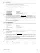
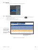
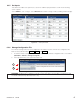
Figure 40 — Group mapping interface
The groups of inverters can then be monitored as a unit in the View Group Status screen.
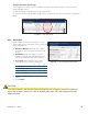
green
black
red
orange
Ensure phases are congured correctly before
mapping inverters in the new groups and turn-
ing them on.
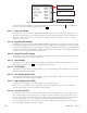
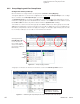
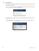
Figure 41 — Monitoring AC Input Groups, AC Output Groups and DC Input Groups
Clicking the black
Flash Module Light
icon to the left of
the module number
causes the LEDs on
the inverter module to
blink briefly.
Loading ratio % value for AC
Output Groups is the higher
value of the two – kW and kVA.
6.4.2 Group Mapping and View Group Status
Configuration of AC Input Groups
Use this interface to assign inverters to input phases (Inverters > Group Mapping).
The logical approach is to match the configuration of inverters in the AC Input Groups to the configu-
ration of inverters in the AC Output Groups as shown in Figure 40.
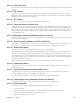
The AC Output Groups of an inverter in the ON state cannot be changed. The radio buttons for that
inverter AC output group remain disabled until the inverter is turned OFF. All inverter modules can be
turned ON or OFF simultaneously with the button under the System Power heading.
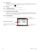
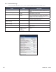
The number of columns increase when groups are added and decrease when groups are removed.
Adding/removing groups (columns) may take a few seconds to update the screen. Changing the ra-
dio buttons (rows) will also take time to apply the changes; for example, approximately two seconds
for one inverter and up to ten seconds for the maximum 32 inverters.