
Manual


61
0700015-J0 Rev B
Fan Fail Alarm (for Fan
Cooled Systems)
Triggers an alarm when a fan fail (speed error or failed fan) condition has
occurred in any of the rectifiers in the system.
• The Fan Fail Alarm is true when the CXC receives a Fan Fail or Fan
Speed Error alarm from any rectifier.
• The Fan Fail Alarm is cleared when all Fan Fail and Fan Speed Error
alarms are cleared from all the rectifiers.
• Each time that the Fan Fail Alarm goes on/off, the event is logged in the
Event History. Since it is a rectifier alarm, up to nine rectifiers (up to 27
fan fail alarms) that are in alarm are logged. If more than nine rectifiers
are in alarm an additional entry is made indicating the total number of
rectifiers in alarm.
The activation value is factory set.
Power Save
Sets an alarm condition when a rectifier is in Power Save mode. The
activation value is factory set.
Urgent AC Mains Fail
Sets a major alarm condition when the Rectifier AC Mains Fail alarm has
been active for a period of time; the default activation value is ten (10)
minutes (see 2.1).
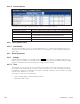
6.6.4.2 Digital Alarms
Each digital input channel is designed to detect zero-system voltage (i.e. off/on) signal. Six of the digital
channels have assigned functions, while two are unassigned. Table D summarizes the digital channel
assignments.
Note that the number of digital inputs varies with hardware. the CXCU and CXCI, for example, have six
only.
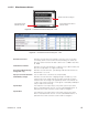
Table D — Digital input channel assignments
Channel Description Factory Default Designation
DIG1 (D1 on PCB) Distribution Fuse/Circuit Breaker
DIG2 (D2 on PCB) Battery Fuse/Circuit Breaker
DIG3 (D3 on PCB) LVD Manual In
DIG4 (D4 on PCB) LVD Manual Out
DIG5 (D5 on PCB) Converter Fail
DIG6 (D6 on PCB) Converter I/P Breaker Trip
DIG7 (D7 on PCB) Digital 7 (unassigned)
DIG8 (D8 on PCB) Digital 8 (unassigned)
Digital events occurring on one of the digital inputs can be programmed to the output alarm relays using
the programming feature for the relay contact similar to analog alarms.
The status of each digital input is visible under the Signals menu; see “LCD Menu structure” on page 17, or
in the web interface go to Main Menu > Signals > View Status.
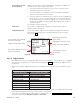
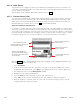
Tap the Activation Value to edit with
the virtual numeric keypad.
Toggle check boxes to select option.
When selecting SNMP, the severity level
(numeric) can also be set.
Discard changes and return to
previous screen
Relay Mapping – N/A or relay 1 to 16
Priority – Major, Minor or Message.
Accept changes and return to
previous screen
Figure 65 — Configure Urgent AC Mains Fail Example