
Manual


0700015-J0 Rev B
66
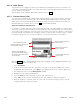
Next, disable the regular AC alarms (6.6.5.2).
Finally, create custom alarms using the average phase voltages. Here is one possible equation:
([Average AC Phase R] < 240) | ([Average AC Phase R] > 300)
Scheduler Usage
The controller has basic scheduling capability that is implemented by using a System Time or System
Date signal in any customizable equation; used to trigger external events on a timely basis, whether daily
or at a specific date.
This is accomplished by using the System Time or System Date signal as an operator in a Custom Alarm
equation, which has been configured to change the state of a relay output. The equation can include any
other signals such as battery current or voltage for more advanced control. The System Time or System
Date signal can only be used with the following operators: ">", "<", and "=".
The formats used for the Time and Date Operands are very specific and must match exactly in order for
an equation to be valid. For the System Time the format is <<hh.mm.ss>> and for System Date the format
is <<20YY.MM.DD>>. The "20" prefix for the year is what distinguishes the date from the time so it must
not be omitted when entering a Date Operand.
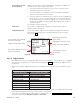
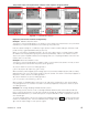
Example 1: The following equation in a Custom Alarm causes the alarm to be true for ten seconds (10 s)
at 2:35 AM:
[System Time (HH.MM.SS)] > <<02.35.00>> & [System Time (HH.MM.SS)] < <<02.35.10>>
If the alarm is mapped to a relay, the relay will activate for 10 sec.
Example 2: Another example activates the alarm daily at 23:59:45 and clears when the battery voltage
is less than 46 V. This is the equation for the alarm named Custom 2:
(([System Time (HH.MM.SS)] > <<23.59.45>>) | ([Custom 2] > 0)) & ([Battery Voltage] > 46)
Note the term: ([Custom 2] > 0). This is to latch the alarm ON since the term: ([System Time (HH.
MM.SS)] > <<23.59.45>>) will evaluate to false once the midnight rollover* (<<00.00.00>>) happens.
*Midnight Rollover is described with an example in 6.7.2.7.
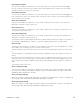
Example 3: We can use the previous example along with a Counter to set the alarm to activate every
three days. These are the equations for Counter 1:
Count Event "[System Time (HH.MM.SS)] > <<01.00.00>>"
Reset Event "[Counter 1]>2"
The will cause Counter 1 to count once daily at 01.00.00. When the count gets to three, it is immediately
reset back to zero. So, every third day, the count returns to zero.
Our Custom 2 alarm equation can now be:
(([System Time (HH.MM.SS)] > <<23.59.45>>) | ([Custom 2] > 0)) & ([Battery Voltage] > 46) & ([Counter
1] = 0)
The resulting behavior will be similar to that in Example 2, except the alarm will only activate once every 3
days.
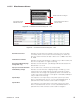
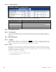
The following sub-section describes the converter alarms menu headings and the associated
items.
6.6.5.8 Converter Alarms
Converter Fail
This menu item enables the Supervisor to set an alarm condition for a true or actual converter failure. The
activation value is factory set.
Converter Minor
This menu item enables the Supervisor to set an alarm condition for a minor converter failure; i.e., an
alarm condition detected in a converter, but one that is not considered an immediate threat to the opera-
tion of that converter. The activation value is factory set.