
Manual

0700015-J0 Rev B
90
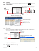
6.8.1.1 DOD Activation
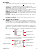
This menu item (LVD DOD Control) allows the Supervisor to configure each LVD control for activation
once the percentage of Depth of Discharge (DOD) has increased above a threshold. This control works
in conjunction with the existing LVD countdown timer and the disconnect voltage. Whichever programma-
ble parameter is met first, the LVD will be activated. Typically, LVD DOD control is needed when ac mains
fails, battery monitor is enabled, battery has discharged for more than one (1) minute and DOD has risen
above the threshold. If DOD activates LVD, then the low voltage connect (LVC) causes reconnect.
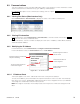
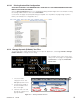
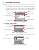
6.8.2 LVD Inhibit
The LVD Inhibit feature provides the means to temporarily prevent all LVD controls from activating without
disabling the LVDs altogether, see example below. The Supervisor will then have 10 minutes to assess
and correct the condition(s) causing the LVD activation.
This menu item differs from other controls in that it cannot be disabled; “Enable Alarm” is grayed out.
With that exception, the remainder of the configuration is similar to all other controls (relay mapping, etc.),
see Figure 81 above. It is logged in an identical manner, except that the only possibilities are ACTIVE and
INACTIVE. Selection will be in effect real-time and not saved – resets on power off.
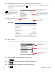
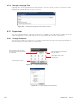
Operation Example:
1. LVD condition occurs.
2. Audible alert sounds and a pop-up window will appear on the GUI prompting the user to “Inhibit
LVDs.”
3. For up to 60 seconds, LVD Inhibit may be evoked by the Supervisor. A password prompt (with
counter) will appear as required.
4. Selecting “Cancel” will reset the 60-second countdown; otherwise, if this time should expire, the LVD
Control will proceed to disconnect the load as configured.
5. Once evoked, LVD Inhibit control, now ACTIVE, will prevent LVD controls from activating for 10
minutes.
6. LVD condition is corrected by Supervisor or LVD Inhibit may be evoked again.
7. Once LVD condition is corrected, LVD Inhibit must be reset manually as required.
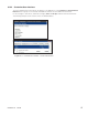
6.8.3 HVSD
This menu item enables the Supervisor to program the setting for a HVSD control, which energizes a re-
lay that can shut down one or more rectifiers when the output voltage exceeds the Activation Value. The
output from HVSD relay is connected to the Remote Shutdown input on the rectifier cabinet. An alarm is
also activated and the message HIGH VOLTAGE SHUTDOWN will display on the CXC’s GUI.
6.8.4 CEMF
The CEMF Cell is a stand-alone panel; which is used to reduce the load voltage (by up to 3.0Vdc) to
protect sensitive loads from high voltages during battery equalize and float cycles.
6.8.4.1 Bypass Voltage
This menu item enables the Supervisor to set the voltage breakpoint to close the CEMF relay and bypass
the CEMF cell (or diode); to directly connect the load to the rectifiers without voltage drops.
6.8.4.2 In-Circuit Voltage
This menu item enables the Supervisor to set the voltage breakpoint to open the CEMF relay and con-
nect the CEMF cell (or diode); to give the appropriate voltage drop to protect the load connected to the
rectifiers.