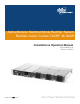
Alpha Modular Switched Mode Rectifier System Rectifier model: Cordex CXCRF 48-300W Installation & Operation Manual Part # 0300072-J0 Effective: 10/2012 member of The Group™ Your Power Solutions Partner
Alpha Modular Switched Mode Rectifier System Rectifier Model: Cordex CXCRF 48-300W NOTE: Photographs contained in this manual are for illustrative purposes only. These photographs may not match your installation. NOTE: Operator is cautioned to review the drawings and illustrations contained in this manual before proceeding. If there are questions regarding the safe operation of this powering system, contact Alpha Technologies or your nearest Alpha representative.
IMPORTANT SAFETY INSTRUCTIONS SAVE THESE INSTRUCTIONS 1. Please read this manual prior to use to become familiar with the product’s numerous features and operating procedures. To obtain a maximum degree of safety, follow the sequences as outlined. 2. This manual provides warnings and special notes for the user: a. Points that are vital to the proper operation of the product or the safety of the operator are indicated by the heading: WARNING. b.
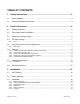
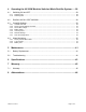
TABLE OF CONTENTS 1 Safety Instructions ..................................................................................... 4 1.1 Safety Symbols .............................................................................................................. 4 1.2 General Warnings and Cautions .................................................................................... 4 2 Product Overview ....................................................................................... 6 2.
4 Operating the 48-300W Modular Switched Mode Rectifier System ....... 28 4.1 Switching ON and OFF ................................................................................................ 28 4.2 Rectifiers 300 W: CXRF 48-300W................................................................................ 28 4.3 Comp@s Settings ........................................................................................................ 29 4.4 Alarm Monitoring .....................................
1 SAFETY INSTRUCTIONS SAVE THESE INSTRUCTIONS This manual contains important safety instructions that must be followed during the installation, servicing, and maintenance of the product. Keep it in a safe place. Review the drawings and illustrations contained in this manual before proceeding. If there are any questions regarding the safe installation or operation of this product, contact Alpha Technologies or the nearest Alpha representative. Save this document for future reference. 1.
• The 48-300W Modular Switched Mode Rectifier System uses more than one live circuit. DC power may be present at the outputs even if the system is disconnected from the mains supply. • In high ambient temperature conditions, the surface of the shelf can be very hot to the touch. • Battery installation and servicing should be done or supervised by personnel knowledgeable about batteries and their safety procedures. • Be extra cautious when connecting or adjusting battery cabling.
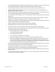
2 PRODUCT OVERVIEW 2.1 General Overview The user manual explains the installation, interconnections and operation of Alpha Technologies 48-300W Modular Switched Mode Rectifier System. Listed below are the possible product configurations: 2.
NOTE Details of controller operations are provided in the latest version of the Comp@s software manual. Figure 2 : Stand-alone energy system including controller with front access communication board Mains input options for the stand-alone energy system: 2.4 IEC Input Voltage Europe: 190 – 250V ̴ nom. USA/Canada: 100 – 250V ̴ nom. Max. input voltage is -10% / +6% of nominal input voltage range 2.4.
NOTE: IEC C16 is a high temperature inlet which requires IEC C15 plug IEC input voltage limitations are shown in section 2.4 2.5 Overview of Control Unit Configurations 2.5.1 Basic units MCU0348M4: Monitoring and control unit with LCD display. Unit features USB and Ethernet port connectors for the communication card. Display indications: output voltage, rectifiers and battery current. Comp@s: Remote communication card with basic package.
• 3 Battery alarm Red LED indicates a battery failure • 4 AC fail alarm Red LED indicates a mains failure 2.6.1.2 USB PORT The USB port is designed for connecting a computer to the system controller via a standard USB cable (type A/B), with direct access to the Comp@s software (Comp@s card required). 2.6.1.3 ETHERNET PORT The Ethernet port is designed for connecting the controller to a user supplied network (TCP/IP secured by the user) via an RJ-45 jack and a standard network cable. 2.6.1.
2.6.3 System controller (MCU with LCD screen) Figure 6 : System controller This controller board offers the same functions as the low profile MCU. Connectors for digital inputs and alarms (signals IN/OUT) are located at the back of the shelf. 2.6.3.1 LCD SCREEN The LCD screen displays the values of: • DC bus voltage [V] • Total rectifier output current [A] • Battery current [A] + = Charging – = Discharging 2.6.3.
Figure 7 : LVD Disconnected 2.6.3.5 LEDS The monitoring module has six LEDs located on the front panel. These are used to display the status of the controller, LVD, system and battery: • Controller status Green LED indicates MCU and Comp@s functions are OK. Green LED is blinking if no Comp@s is present. • LVD OK Green LED indicates the LVD (low voltage disconnection) is closed. If the LED remains OFF, it means the LVD is open.
2.6.4.1 TEMPERATURE SENSOR (BATTERY) Temperature probe input for battery temperature compensation. 2.6.4.2 54V DC OUTPUT WITH ALARM-INDICATING FUSES 4 outputs are available on the distribution unit, protected by alarm-indicating fuses. The available fuse ratings are 2A, 5A and 10A and these can be ordered from Alpha Technologies. When a fuse is blown, a coloured dot indicates the circuit is open.
2.6.4.6 LED When the green LED is on, the LVD is active (closed). When the LED is off, the LVD is not active (open). 2.6.5 Cordex Rectifier CXRF 48-300W Figure 9 : Cordex Rectfier 2.6.5.1 LED RECTIFIER STATUS INDICATOR The LED indicates the status of the rectifier: • Green LED Normal conditions • Orange LED Stand-by (remote on/off) • Red LED Low output voltage • Red blinking LED Failure (mains, temperature, output short circuit) 2.6.5.
2.7 Mechanical Overview 2.7.
2.
3 INSTALLATION 3.1 Site Planning CAUTION Restricted Access: the 48-300W Modular Switched Mode Rectifier System must be installed in a restricted area accessible by qualified service personnel only. CAUTION Grounding: the 48-300W Modular Switched Mode Rectifier System must be correctly grounded for proper operation. Older facilities may have inadequate electrical grounding.
3.2 Safety Markings This equipment is a Class 1 appliance. Applicable standards: CE marking for Low Voltage Directive 73/23/EEC. • • EN 60950-1, CEBEC approval pending.
3.3 Installation This part is provided for the guidance of qualified personnel to install the product, which shall be mounted in a clean and dry environment. 3.3.1 Safety Precautions WARNING! Hazardous voltages are present at the input of power systems. The DC output from the rectifiers and battery system, though not dangerous in voltage, has a high short circuit current capacity that may cause severe burns and electrical arcing. 3.3.
Chassis support Figure 12 : Mounting the shelf 3.3.4 Ventilation The CXRF 48-300W features a forced air cooling. The air flow goes from front to rear. It is necessary to keep a minimum free space in front and behind the shelf. This space must be at least 15mm. Front 15mm 15mm Figure 13 : Ventilation of the shelf 3.3.5 Wiring Procedure WARNING! Make sure the line power is off.
Signals If used, make the Ethernet connection via the port on the front of the controller (Figure 14) and signal connectors at the rear of the shelf (Figure 15) Figure 14 : Front ethernet port Figure 15 : Rear signal connectors Optionally, a set of mating connectors can be provided with the system. Figure 16 : Signal connector pinning The following table lists all the pin assignments for the signal connectors: X110 Name Remarks 1 -- 2 -- 3 0 V signal 0V signal for Temp.
8 Dig_Out2_n_closed X112 Normally closed contact of potential free alarm 2 Name Remarks 1 Dig_Out3_common Common point of potential free alarm 3 2 Dig_Out3_n_open Normally open contact of potential free alarm 3 3 Dig_Out3_n_closed Normally closed contact of potential free alarm 3 4 Dig_Out4_common Common point of potential free alarm 4 5 Dig_Out4_n_open Normally open contact of potential free alarm 4 6 Dig_Out4_n_closed Normally closed contact of potential free alarm 4 7 -- 8 --
X104 Name Remarks 17 Dig_Out2_common Common point of potential free alarm 2 18 Dig_Out1_common Common point of potential free alarm 1 19 -- 20 -- 21 -- 22 -- 23 Dig_Out4_n_closed Normally closed contact of potential free alarm 4 24 Dig_Out3_n_closed Normally closed contact of potential free alarm 3 25 Dig_Out2_n_closed Normally closed contact of potential free alarm 2 26 Dig_Out1_n_closed Normally closed contact of potential free alarm 1 DO NOT CONNECT Table 2 : Sub-D26 signal
Figure 20 : Rear DC bus connector DC Bus + - NOTE: On delivery, the “+” pole of the DC bus is FLOATING (i.e. NOT connected to earth). In order to comply with the SELV (Safety Extra Low Voltage) rules, the “+” DC bus must be connected to earth. 3. Auxiliary DC output: Each rectifier has a front panel mounted DC output. The polarity is indicated on the front plate. Insert the wires in the mating connector and secure them by tightening the screws located on top of the connector.
Mains input Connect the mains to the 48-300W Modular Switched Mode Rectifier System AC input according the shelf configuration. Please observe the following recommendations: • Pigtail (1.5m cable): first connect the yellow/green protective earth cable to the protective earth of the mains before connecting the neutral and line.
Battery (only for stand-alone systems) WARNING! The batteries must be installed by qualified personnel trained in the safe use of high-energy power supplies and batteries. Refer to product safety information. WARNING! The external battery MUST be protected according to the system power and the installed cross-section of the cables. The fuse or disconnecting device must be capable of interrupting the current in the event of a short-circuit.
5. Verify the battery connector polarity and DC voltage with a DC voltmeter. If correct, plug it into the battery connector at the front of the distribution unit (Figure 25). 6. Route the sensor end of the battery temperature cable to the batteries. Tape it to the side of the centre of the batteries string. As the cable terminal is voltage free, the sensor can even be placed directly on one of the copper bar inter-cell links.
3.3.
4 OPERATING THE 48-300W MODULAR SWITCHED MODE RECTIFIER SYSTEM 4.1 Switching ON and OFF 4.1.1 Switching ON After powering up the 48-300W Modular Switched Mode Rectifier System, please verify that the following: • The mains is ON. • The rectifiers correctly report mains present. (Green LEDs on each rectifier should illuminate). • If the system is fitted with a Comp@s board, after 30 seconds the leftmost LED should be permanently ON Note: LED continues to flash if no Comp@s is present.
Colour Pulse freq. State (Hz) Green Permanent OK Orange Permanent REMOTE_OFF Red Permanent DC_NOT_OK Red Flashing (2) MAJOR_FAULT Description Normal conditions : Uout within specifications Normal conditions: in standby = OFF DC voltage is below minimum rated voltage (36 V) The power supply is interrupted by one of the following causes: • AC voltage out of range ≥ 285 V • Internal temperature too high • Output short-circuit longer than 10 sec Table 3 : Rectifier LED indication 4.
Table 4 summarises the features of each license (for more details refer to the Comp@s manual). Description License 1. Basic 2. Battery 3. Asset 4. Modbus Float voltage, TC, LVD Boost functions DC Bus alarms Battery continuity Battery temperature Battery max.
Min. Current for Discharge Alarm -2 Amps x Boost Automatic False x Boost Activation Low Voltage 46.0 Vdc x Boost Termination Voltage 56.4 Vdc x When reached ; back to Float Boost Termination Current 2 Amps x When reached ; back to Float Boost Termination Time 120 minutes x When reached ; back to Float Battery Test (BT) End Voltage 46.
Figure 28: Bs voltage 4.3.4 Battery Setup The battery and related alarms can be configured individually. Temperature compensation The bus voltage (and hence the battery charging voltage) can be automatically adjusted proportionate to the ambient temperature around the batteries. The value of this compensation is given by the battery manufacturer. Note that the compensation is usually given per 2V cell.
Figure 30: Battery setup Battery pre-alarms Alarms are generated when the DC Bus voltage reaches one of the pre-set alarm levels. In this case, no action is initiated other than an alarm (major, minor or battery) being generated on the MCU LEDs and the corresponding relay. 4.3.5 LVD Trip Level During a battery discharge the internal LVD opens when the battery low voltage trip level is reached. The factory settings for this are the following: Description Factory setting trip level MCU settings 43.
If more than one rectifier is installed in the system and the load is significantly less that the full rated capacity of the installed rectifiers (e.g. load is on stand-by) the Smart Energy function can be activated in order to limit the power consumption and increase the system efficiency. The Smart Energy function turns off unused rectifiers, depending on the load activity. If a rectifier is in standby, an orange LED on its front panel will be illuminated.
4.3.7 Save the Configuration Once the configuration has been modified, it needs to be saved. If not, the new settings will be lost once the MCU is switched off (no DC supply). The settings are temporarily saved in the Comp@s Card until you save the data into the MCU.
4.4 Alarm Monitoring 4.4.1 Factory Preset Alarm Table Table 7 contains the default alarms in the MCU. ID Description 1. DC Bus Extra Low 2. DC Bus Low X 3. DC Bus High X 4. DC Bus Extra High X 5. DC Bus Voltage Sense Failure X 6. Mains Failure X 7. Mains Partial Failure X 8. Mains Low X 9. Not used 10. One rectifier Failure 11. More than One Rectifier Failure X 12. Missing Rectifier (with Comp@s) X 13. Battery Last Test Failed X 14. Battery on discharge X 15.
4.4.2 Type of Alarm There are 5 different alarm types: • Warning • Minor • Major • Critical • Disabled For each type of alarm, a severity level between 0 and 9 can be assigned (fully user configurable). Each alarm can also be associated to a relay. Each relay controls one LED. There are four possibilities.
Figure 34 below illustrates some alarm and relay associations: Figure 34: Alarms 4.4.3 Battery Test Depending on the Comp@s license procured with the system, there are two different battery tests. 4.4.3.1 BATTERY CONTINUITY CHECK This check is part of the Basic License. When the test is manually started, the output of all installed rectifiers is set to deliver a low output voltage (lower than the battery voltage). The batteries are discharged by the load current.
4.4.3.2 BATTERY TEST NOTE: The Battery License is required to perform a full battery test. The battery test starts when: • the time period between two automatic tests is reached (see Comp@s user manual for more details) OR • the “BATT TEST” button is pressed for a period of more than 5 seconds. During the test, the green “LVD ON” LED flashes.
Figure 35: Comp@s - Battery test Table 10 lists the actions for conducting a battery test: Status Conditions Start Battery Test Actions Test Time Interval reached Battery test button pressed more than 5sec.
5 MAINTENANCE 5.1 Battery Replacement WARNING! Use insulated tools when working with batteries. WARNING! Ensure that the system is connected to the mains. The following procedure should be followed to change the batteries when the system is connected to an AC supply: 1. Check that the rectifiers are delivering power and that the output voltage is 54Vdc (+/- 0.5Vdc). 2. Open the system battery breaker. 3. Open the external battery disconnect device (if present) 4.
5.2 Troubleshooting If any red LEDs on the front panel of the MCU are illuminated this indicates that a fault has developed in the 48300W Modular Switched Mode Rectifier System. Table 11 provides a summary of system alarms: Alarm submenus Alarm Description of problem What to do Battery temperature high The battery temperature is above the specified limits Ensure that the battery cooling system (if used) is working.
6 SPECIFICATIONS Power Module Output Voltage 40 to 58 Vdc within rated limits Power 300 W Maximum Operating voltage without damage 300 Vac Current 5.6A @ -54Vdc 6.7A @ -45V Hold-up Time >10ms Electrical noise <10mVrms (wideband) <2nV (psophometric) Acoustic noise 49 dBA Power Module Input Voltage Operating Range 90 to 265 Vac Maximum operating voltage without damage 300 Vac Frequency 47 to 63.6 Hz Current 1.40A @ 230Vac 3A @ 110Vac 3.
Shelf dimensions 43mm H x 439mm W x 237 D (with rectifier 250mm D 1.7” H x 17.3” W x 9” D (with rectifier 9.84”D) Mounting 19” or ETSI Earth M6 male stud on the rear of the shelf Shelf weight (including controller and DC distribution) 2.8 KG (6.2 lb) Rectifier power module weight 0.57 Kg (1.2 lb) Agency Compliance Safety CSA C22.2 No.
7 WARRANTY Visit http://www.alpha.ca/web2/services-and-support/warranty.html for full warranty information. 7.1 Warranty Alpha Technologies Ltd. warrants all equipment manufactured by it to be free from defects in parts and labor, for a period of two years from the date of shipment from the factory.
8 ABBREVIATIONS NOTE: This table does not contain all standard abbreviations.
Alpha Technologies Ltd. 7700 Riverfront Gate Burnaby, BC V5J 5M4 Canada Tel: +1 604 436 5900 Fax: +1 604 436 1233 Toll Free: +1 800 667 8743 Alpha Energy, Alpha Technologies Inc. 3767 Alpha Way Bellingham, WA 98226 United States Tel: +1 360 647 2360 Fax: +1 360 671 4936 Alpha Industrial Power Inc.