Alpha Modular Switched Mode Rectifier System Rectifier Models: Cordex CXRF 48-3.
Modular Switched Mode Rectifier System Models: Cordex CXRF HP 48-12kW Cordex CXRF HP 48-4.0kW Cordex CXRF 48-3.6kW NOTE: Photographs contained in this manual are for illustrative purposes only. These photographs may not match your installation. NOTE: Operator is cautioned to review the drawings and illustrations contained in this manual before proceeding. If there are questions regarding the safe operation of this powering system, contact Alpha Technologies or your nearest Alpha representative.
Table of Contents 1. 2. 3. Safety ������������������������������������������������������������������������������������������������������������������������������������5 1.1 Safety Symbols �������������������������������������������������������������������������������������������������������������������������� 5 1.2 General Safety ��������������������������������������������������������������������������������������������������������������������������� 5 1.
4.6 Alarm and Control Output Relays �������������������������������������������������������������������������������������������� 17 4.7 System Fail Alarm/Relay ���������������������������������������������������������������������������������������������������������� 17 5. Inspection ���������������������������������������������������������������������������������������������������������������������������18 5.
10.4 Fan and Fan Filter Replacement ������������������������������������������������������������������������������������������� 33 10.5 MOV Replacement ����������������������������������������������������������������������������������������������������������������� 37 11. Acronyms and Definitions ��������������������������������������������������������������������������������������������������41 12.
1. Safety SAVE THESE INSTRUCTIONS: This manual contains important safety instructions that must be followed during the installation, servicing, and maintenance of the product. Keep it in a safe place. Review the drawings and illustrations contained in this manual before proceeding. If there are any questions regarding the safe installation or operation of this product, contact Alpha Technologies or the nearest Alpha representative. Save this document for future reference. 1.
1.4 Electrical Safety WARNING! Hazardous voltages are present at the input of power systems. The DC output from rectifiers and batteries, though not dangerous in voltage, has a high short-circuit current capacity that may cause severe burns and electrical arcing. • Before working with any live battery or power system, follow these precautions: a. Remove all metallic jewelry, such as watches, rings, metal rimmed glasses, or necklaces. b.
2. Introduction 2.1 Scope of the Manual This instruction manual explains the installation, interconnection, and operation of the Alpha Cordex 48-3.6kW, 48-4.0kW and 48-12kW modular switched mode rectifier systems. 2.2 Product Overview A complete Cordex rectifier system consists of one or more power modules in a common shelf enclosure. The shelf has connections for AC inputs, DC output, and system communications.
2.3 Part Numbers and List Options The product, options, and accessories can be ordered by using the following part numbers: 8 Description List Option Cordex 48-12kW rectifier power module 0100002-002 Basic module *List 0 Fan, spare for Cordex 48-12kW 747-679-20 Fan filter, spare for Cordex 48-12kW 747-652-20-060 MOV assembly, spare for Cordex 48-12kWt 707-813-20 Cordex 48-3.
Description List Option Kydex rear cover List 89 Module blank List 90 CXCM4 Cordex Controller, Modular, 4RU, takes the space of one rectifier (pre-RoHS # 018-574-20) 018-586-20 Basic unit *List 0 48 V system [requires a connection interface (747-271-20) for modular installation] List 2 Standard temperature (0 to 65ºC) List 40 Extended temperature (-40 to 65ºC) *List 42 Gray finish with blue silkscreen *List 50 Charcoal finish with gray silkscreen List 56 Expanded Flash memory List 110
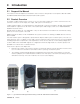
3. Rectifier Features 3.1 Front Panel The three LEDs on the rectifier front panel indicate status: • AC ON (1) • DC ON (2) • Alarm (3) LEDs 1 2 3 LEDs 1 2 3 Thumbscrew 3.
3.1.1 Rectifier LEDs The front panel LEDs indicate: • Rectifier status summary • Rectifier software upgrade in progress • Patterned response to Locate Module command The rectifier status summary shows the rectifier alarm status, communication fail status, and rectifier on/off status. AC ON (1) The green LED is illuminated when the AC input voltage is within its allowable range. The LED flashes (~2Hz) when input voltage is outside the allowable range.
3.2 Rectifier Rear Panel A single connector for shelf power and communications is located on the rear panel of each rectifier. The 12kW rectifier has three connectors. 3.3 True Module Fail Alarm The power modules have a “true” fail alarm that provides a true indication of the power module’s ability to source current. When the module’s output current drops below 2.5% of the rated output, a low output current condition is detected and the Module Fail detection circuit is activated.
3.7 AC Inrush/Transient Suppression To prevent a surge on the AC inout line, the inrush current of a rectifier module is limited to the full load steady state line current. Modules are also protected from input lightning and transient surges in accordance with IEEE/ ANSI C62.41 Category B3 standards. 3.8 Soft Start A soft start feature is used to eliminate an instantaneous demand on the AC power source.
4. Cordex System Controller (CXC) 4.1 CXCM4 Features The CXCM4 (Cordex Controller, Modular, 4RU) is mounted in the rectifier system shelf and brings advanced monitoring technology to the Cordex series of rectifiers. This compact system controller is designed for seamless operation and set up for Alpha power systems.
LEDs The three LEDs, located on the CXCM4 front panel, display the alarm status of the power system, CXCM4 progress and status during startup, and file transfers. Alarm Conditions The CXCM4 illuminates the LED that corresponds to the system alarm status. Each LED color corresponds to a specific alarm status (only one LED is illuminated at a time during alarm conditions.) Green OK, no alarms present. Yellow Minor alarm is present, no major alarms. Red Major alarm is present.
4.3 Rectifier Report from Controller Display To display the installed rectifiers and their status, logon through the controller interface. From the Main Menu, select Rectifiers > Rectifier Report to generate the report screen for all acquired modules in the system (Figure 4). Tapping on a rectifier in the screen generates a Rectifier Locate command that causes the rectifier's LEDs to flash briefly. FL + TC 54.
4.5 Digital Input Channels The CXCM4 can accommodate up to four channels and can monitor digital alarm/control signals from rectifiers, converters, and other types of equipment. 4.6 Alarm and Control Output Relays The CXCM4 contains eight Form-C digital alarm output relays that are used to extend alarms and to control external apparatus. Each internally generated alarm or control signal can be mapped to any one of the relays, or several signals can be mapped to just one relay or none at all. 4.6.
5. Inspection 5.1 Packing Materials All Alpha products are shipped in rugged, double walled boxes and suspended via solid inserts to minimize shock that may occur during transportation. Packaging assemblies and methods are tested to International Safe Transit Association standards. Rectifiers and batteries are shipped on individual pallets and are packaged according to the manufacturer’s guidelines. 5.1.1 Returns for Service Save the original shipping container.
6. Installation The equipment is suitable for installation in Network Telecommunication Facilities. WARNING! This system is designed to be installed in a restricted access location that is inaccessible to the general public. The following procedure is written for qualified personnel to install this product in a clean and dry environment. For the battery installation, refer primarily to the manufacturer’s manual. 6.
6.3 Power System Assembly and Mounting 6.3.1 Shelf Preparation/Mounting NOTE: Mount the shelf in a clean and dry environment. Allow at least 1.75” of free space in front of the unit for unrestricted cooling airflow. Sufficient free space must be provided at the front and rear of the power system. This is to meet the cooling requirements of the rectifiers and to allow easy access to the power system components. The 19” shelf has been designed for flush mounting in a standard EIA relay rack.
7. Wiring This chapter provides cabling details and notes on cable sizing for DC applications using the Cordex 48-3.6kW, 4.0kW and 12kW modular switched mode rectifier systems. Refer to the Safety section on page 5 for safety precautions. WARNING! Ensure that the power at the AC service panel is off is switched off. Remove battery line fuses or connections before attempting work on the wiring. Use a voltmeter to verify the absence of a voltage.
7.3 AC Input Connections CAUTION! To minimize EMI disturbances, route the AC input wires in flexible or rigid conduit and located as far away as possible from the DC power wires. WARNING! Use care when removing or replacing the covers for the AC input connections. Never assume that an electrical connection or conductor is not energized. 1. Ensure that all modules are removed from the shelf. 2.
7.5 CAN Serial Ports (Rectifier Shelf) Two CAN Serial ports (modular jacks with offset latches), are provided for communications with Alpha’ Cordex rectifiers and other CAN-enabled equipment. These are located on the left side of the rectifier shelf as viewed from the front. Daisy-chain from shelf to shelf (CAN OUT of one shelf to CAN IN of another) and ensure that only the last shelf is terminated. 7.5.
7.6 Inserting the CXCM4 Module NOTE: Do not force a module into position if it does not seat properly. All modules are keyed to ensure that the correct module (voltage/polarity) type is used. 1. Insert by placing the controller on the shelf bottom and sliding the module into the CXCM4 connection interface (inside of the shelf, see drawing 747-271-08). 2. Apply pressure on the metal faceplate to engage the rear connectors. 3.
7.7.2 Digital Inputs The digital input channels are used to monitor various alarm and control signals. All input channels are voltage activated and accept a bipolar (negative or positive) DC signal directly. Connection Method Typical Alpha systems use the “reset with Hot and trigger with Ground” connection. The digital input is wired in such a way that the Hot is wired directly into one of the input terminals. For example, the positive input for +24 V systems.
Voltage Input #2 (battery voltage per CXC software) is wired internally (V2) to the rectifier output voltage of the shelf. This is used as the reference for system alarming (such as high voltage) and control (such as low voltage disconnect). Temperature Sensing Temperature Probe input channels provide connections for temperature sensors. A voltage is supplied to these terminals for sensor measurements.
8. System Startup Visually inspect the installation thoroughly. After completing the system installation and power system wiring, perform the following startup and test procedure to ensure proper operation: 8.1 1. Check System Connections Make sure that the AC input power is switched off, the batteries are disconnected, and all the power modules are removed from the shelf. 2. Triple-check the polarity of all connections. 8.
9. Rectifier States, Modes and Factory Defaults 9.1 Main Rectifier States The rectifier operation can be broken up into five main states: 1. Off. 2. Start delay. 3. Soft start. 4. Normal operation. 5. Switching off. Each state is characterized as being distinct and necessary for the operation of the rectifier. These states are briefly described below. 9.1.1 Off State The rectifier is in the Off state immediately after power is applied to the rectifier or after a rectifier shutdown.
9.2 Main Rectifier Modes In addition to the main rectifier states, there is a set of main rectifier modes. These modes can be divided into two categories, the output voltage mode and the output current/power mode. 9.2.1 Output Voltage Modes Voltage modes can be thought of as modes that, under software control, can directly adjust the output voltage.
9.3 Factory Ranges and Defaults Table D shows the rectifier settings/ranges/defaults. Changes are made through the CXC interface. Table D — Rectifier factory ranges and defaults Setting Range (minimum to maximum) Default Float (FL) Voltage 47.5 – 58.2 V 54 V Equalize (EQ) Voltage 49.8 – 60.
10. Maintenance Although very little maintenance is required with Alpha systems, routine checks and adjustments are recommended to ensure optimum system performance. Qualified service personnel should do the repairs. The following table lists a few maintenance procedures for this system. These procedures should be performed at least once a year. WARNING! Use extreme care when working inside the unit while the system is energized. Do not make contact with live components or parts.
10.3 Replacing the CXCM4 Module WARNING! Before removing a CXCM4 from a live system, an external LVD override is required to avoid a disruption of service. Figure 8 — LVD override control and distribution alarm card The LVD Control functions can be hardwired directly from the assigned relay output to an optional LVD override control and distribution alarm card (707-307-20). 1. Place the LVD Control switch to the OVERRIDE IN position to keep the LVD contactor engaged. 2.
10.4 Fan and Fan Filter Replacement 10.4.1 4.0kW Rectifier Fan and Filter Replacement Refer to "2.3 Part Numbers and List Options" on page 8 for the part number of the replacement fan assembly and filter. Top screw (1) Front panel Side screws (2) 1. Switch off the unit and unscrew the front fastener that secures the power module to the shelf. 2. Slide the module 10 cm (4") out of the shelf and wait ten minutes for the module capacitors to discharge. 3.
4. Disconnect the fan cables from the module by pulling out the fan cable connector. 5. Remove the two screws that secure the fan to the front panel. 6. Note the direction of the airflow and remove the fan from the front panel. Fan screws Figure 9 — 4kW rectifier fan removal 7. Inspect the fan filter and replace if necessary. Filter Screen Figure 10 — 4kW rectifier fan filter removal 8. Install the replacement fan following the preceding steps in reverse order.
10.4.2 12kW Rectifier Fan Replacement Refer to "2.3 Part Numbers and List Options" on page 8 for the part number of the replacement fan. 1. Switch off the unit and unscrew the front fastener that secures the power module to the shelf. 2. Remove the eight screws shown in Figure 11 Bottom screws (3) Top screws (3) Side screw (1) Side screw (1) Figure 11 — Fan assembly - screw removal 3. Disconnect the fan cables and remove the fan assembly from the rectifier. Figure 12 — Fan assembly 4.
10.4.3 3.6kW Rectifier Fan or Filter Replacement Refer to "2.3 Part Numbers and List Options" on page 8 for the part number of the replacement fan. 1. Shut off the unit and unscrew the front fastener that secures the power module to the shelf. 2. Slide the module 10 cm (4") out of the shelf and wait two minutes for module capacitors to discharge. 3. Remove the four screws (two each side) that secure the front panel to the module chassis. 4. Slide the front panel out. 5.
10.5 MOV Replacement 10.5.1 4.0kW Rectifier MOV Replacement Refer to "2.3 Part Numbers and List Options" on page 8 for the part number of the replacement MOV. The MOVs (metal oxide varistor) are used to protect the power modules from power line surges and surges caused by lightning strikes. High capacity surges may permanently damage MOVs but they are easily replaced in the field using the following procedure: 1. Shut off the unit and unscrew the front fastener that secures the power module to the shelf.
4. Remove the cover and find the MOV printed circuit board (PCB). Insulating mat MOV PCB screws 5. Fold the insulating mat out of the way and remove the three screws that secure the MOV PCB to the module. MOV PCB 6. Remove the MOV PCB. 7. Decontaminate the area and unit with a flux remover or similar cleaning compound. This is done to remove any metallic particles or carbon that may have been deposited when the MOV failed. 8.
10.5.2 12kW Rectifier MOV Replacement Refer to "2.3 Part Numbers and List Options" on page 8 for the part number of the replacement MOV. The MOVs (metal oxide varistor) are used to protect the power modules from power line surges and surges caused by lightning strikes. High capacity surges may permanently damage MOVs but they are easily replaced in the field using the following procedure: 1. Shut off the unit and unscrew the front fastener that secures the 12kW power module to the shelf. 2.
10.5.3 3.6kW Rectifier MOV Replacement Refer to "2.3 Part Numbers and List Options" on page 8 for the part number of the replacement MOV. The MOVs (metal oxide varistor) are used to protect the power modules from power line surges and the surges caused by lightning strikes. High capacity surges may permanently damage MOVs but they are easily replaced in the field using the following procedure: 1. Shut off the unit and unscrew the front fastener that secures the power module to the shelf. 2.
11. Acronyms and Definitions AC ANSI AWG BTU CAN CEC CSA CX DC DHCP EIA EMC EMI ERM ESD FCC GSM HVSD IEC IEEE IP LED LVD MIL MOV MTBF NC NEC NO OSHA OVP RAM RU TCP/IP THD UL VRLA 9400000-J0 Alternating current American National Standards Institute American Wire Gauge British thermal unit Controller area network Canadian Electrical Code Canadian Standards Association Cordex™ series; e.g.
12. 12.1 Warranty and Service Information Technical Support Free Technical Support 24/7/365 is part of the Alpha customer satisfaction commitment. The phone numbers below can also be used to access a wide range of service solutions both at your premise and at the Alpha facility nearest you. In Canada and the USA, call toll free 1-888-462-7487 24 hours a day, seven days a week. Customers outside Canada and the USA, call +1-604-436-5547. 12.2 Warranty Alpha Technologies Ltd.
Specifications for Alpha Switched Mode Rectifier Cordex 48-4kW Power Module Output Voltage: 44 to 60 Vdc within rated limits Current: 74 A @ 54 Vdc nominal (83 A maximum @ 48 V) Maximum Power: 4000 W continuous/module Static Load Regulation: Better than ±0.5% for any load change within rated limits Dynamic Load Regulation: Better than ±2% for 40% - 90% load step (output shall recover to static limits within 10 ms) Static Line Regulation: Better than ±0.
Specifications for Alpha Switched Mode Rectifier Cordex 4kW Power Module Input Voltage: 208, 220, 230, 240, 277 Vac nominal Operational Range: 187 to 320 Vac Extended Operation: Low: 187 to 90 Vac (derated power) Frequency: 45 to 66 Hz Current: 17.5 A @ 240 Vac 21.5 A @ 208 Vac 23.5 A @ 176 Vac (maximum) Recommended Feeder Breaker Single Phase: 30 A, #10 AWG Three Phase: 50 A, #6 AWG delta connection 30 A, #10 AWG wye connection Power Factor: > 0.
Specifications for Alpha Switched Mode Rectifier Cordex 4kW Weight: Module: 3.9 kg (8.6 lb) 23" Shelf: 14.5 kg (32 lb) 19" Shelf: 12.7 kg (28 lb) Safety EN 60950-1: 2006 Rectifier output shall be rated SELV suitable for connection to TNV-1 circuits UL 60950-1: 2 CSA C22.2 No. 60950-1-07 CE EN 60950-1: 2006 CB Scheme 2006/95/EC Low Voltage Directive Telcordia (Bellcore) GR-1089-CORE (requirements applicable to rectifier) nd Ed.
Specifications for Alpha Switched Mode Rectifier Cordex 48-12kW Power Module Output Voltage: 44 to 60 Vdc within rated limits Current: 222 A @ 54 Vdc nominal (249 A maximum @ 48 V) Maximum Power: 12kW continuous/module Static Load Regulation: Better than ±0.5% for any load change within rated limits, under control of Cordex Controller Dynamic Load Regulation: Better than ±2% for 40% - 90% load step (output shall recover to static limits within 10 ms) Static Line Regulation: Better than ±0.
Specifications for Alpha Switched Mode Rectifier Cordex 48-12kW Power Module Input Voltage: 208-240 Vac (3Φ – 3 Wire + PE) Nominal 360-480Vac (3Φ – 3 Wire + N + PE) Nominal 208-277Vac (1Φ) Nominal Operational Range: 187 to 320 Vac (Per Connector AC Input on Module) Extended Operation: Low: 187 to 95 Vac (Per Connector AC Input on Module, Derated Power) Frequency: 45 to 66 Hz Current: 39-30A/Feed (3Φ – 3 Wire + PE) 22-15A/Feed (3Φ – 3 Wire + N + PE) 22-15A/Feed (1Φ) Recommended Feeder Breaker Sing
Specifications for Alpha Switched Mode Rectifier Cordex 48-12kW Dimensions (inches): Dimensions (mm): W10.3 x H6.25 x D11.8 (W10.3 x H7 x D14.38 including front panel and handle) W261 x H160 x D300 (W261 x H177 x D365 including front panel and handle) Weight: Module: 12 kg (27 lb) 23" Shelf: 14.5 kg (32 lb) 19" Shelf: 12.7 kg (28 lb) Safety EN 60950-1: 2006 Rectifier output shall be rated SELV suitable for connection to TNV-1 circuits UL 60950-1: 2 CSA C22.2 No.
Specifications for Alpha Switched Mode Rectifier Cordex 48-3.6kW Power Module Output Voltage: 42 to 60Vdc within rated limits Current: 66.5A @ 54Vdc nominal (75A maximum @ 48V) Maximum Power: 3600W continuous/module Static Load Regulation: Better than ±0.5% for any load change within rated limits Dynamic Load Regulation: Better than ±2% for 40% - 90% load step (output shall recover to static limits within 30ms) Static Line Regulation: Better than ±0.
Specifications for Alpha Switched Mode Rectifier Cordex 48-3.6kW Continued Power Module Input Voltage: 208, 220, 230, 240, 277Vac nominal Operational Range: 176 to 320Vac Extended Operation: Low: 176 to 90Vac (derated power) Frequency: 45 to 66Hz Current: 16.8A @ 240Vac 19.4A @ 208Vac 22.8A @ 176Vac (maximum) Recommended Feeder Breaker Single Phase: 30A, #10AWG Three Phase: 50A, #6AWG delta connection 30A, #10AWG wye connection Power Factor: >0.
Specifications for Alpha Switched Mode Rectifier Cordex 48-3.6kW Continued Weight: Module: 4.6 kg (10.1 lb.) 23” Shelf: 14.5 kg (32 lb.) 19” Shelf: 12.7 kg (28 lb.) Safety EN 60950-1: 2006 Rectifier output shall be rated SELV suitable for connection to TNV-1 circuits UL 60950-1: 2 CSA C22.2 No. 60950-1-07 CE EN 60950-1: 2006 CB Scheme 2006/95/EC Low Voltage Directive Telcordia (Bellcore) GR-1089-CORE (requirements applicable to rectifier) nd Ed.
REVISIONS LIST 89 - KYDEX REAR COVER 16.10 408.8 REV BY LTR DESCRIPTION B CORRECTED NO. OF MODULES EOF 2004/06 WS C INCORPORATED E.O.'S A1-9 J.U. 2005/02 DATE APPD GS D LIST 81 UPDATED MP/JU 2005/10 E CORRECTED VIEWS DESCRIPTION MP WES 2005/10 15.28 388.2 17.16 436 6.00 152.4 LIST 23 23" MID-MOUNT 0 0.93 23.6 201.2 175.8 150.4 125 REAR COVER 0 177 171.1 139.3 126.6 94.9 82.2 50.4 37.7 6 17.17 436 7.92 6.92 5.92 4.92 6.97 6.74 5.49 4.99 3.74 3.24 1.99 1.49 0.
20.13 511.4 15.28 388.2 6.00 152.4 LIST 23 23" MID-MOUNT REAR ISOMETRIC VIEW (LIST 81 - OUTPUT BARS) 0 LIST 25 23" FLUSH MOUNT TOP VIEW 0 4.92 125 6.92 175.8 5.92 150.4 7.42 188.5 13.42 340.9 15.92 404.4 14.92 379 13.92 353.6 (LIST 81 - OUTPUT BARS) 7.57 192.4 6.90 175.1 REAR ISOMETRIC VIEW 0 (LIST 82 - OUTPUT BARS) REAR VIEW THESE DESIGNS AND SPECIFICATIONS ARE THE PROPERTY OF ARGUS TECHNOLOGIES AND SHALL NOT BE COPIED OR USED FOR MANUFACTURING WITHOUT ITS WRITTEN CONSENT.
REVISIONS LTR REV BY DESCRIPTION B LIST 81 UPDATED C CORRECTED VIEWS DESCRIPTION D UPDATED LIST 85 LABELS DATE APPD MP/JU 2005/10 MP 2005/10 WES GS SDW AC WIREWAY BLANK PLATE AC WIREWAY, BOTH SIDES, 1.
3/8" FLAT WASHER 3/8" LOCK WASHER 3/8 - 20 NUT POSITIVE (+) OUTPUT TERMINAL 3/8" FLAT WASHER 3/8" LOCK WASHER 3/8 - 20 NUT POSITIVE (+) OUTPUT TERMINAL DC WIRING (CUSTOMER SUPPLIED) POSITIVE (+) BUS BAR (CUSTOMER SUPPLIED) NEGATIVE (-) OUTPUT TERMINAL NEGATIVE (-) OUTPUT TERMINAL 3/8" FLAT WASHER 3/8 - 20 x 1" HEX BOLT NEGATIVE (-) BUS BAR (CUSTOMER SUPPLIED) REAR ISOMETRIC VIEW - LIST 82 BUS BAR INSTALLATION 3/8" 2 HOLE COMPRESSION TERMINAL 1" SPACING (CUSTOMER SUPPLIED) REAR COVER LIST 89 3/8" F
DESCRIPTION B C REV BY EOF CORRECTED NO. OF MODULES REAR COVER, BLANKING PLATE ADDED D D1 INCORPORATED EO -C1. LIST 19 & 23 ADDED. CORRECTED SPELLING ERROR DATE APPD 2004/06 GS J.U. 2005/02 GS JLM 2006/09 GS JLM 2006/09 0 5.42 137.6 5.92 150.3 6.92 175.7 7.42 188.4 9.86 250.4 10.36 263.1 11.36 288.5 16.10 408.9 15.28 388.2 11.86 301.2 17.40 441.9 0 17.40 441.9 REVISIONS LTR 6.74 171.1 6.55 166.4 6.05 153.7 4.99 126.6 5.05 128.3 LIST 19 MOUNTING OPTION SHOWN 1.99 50.4 .24 6.
REVISIONS LTR B REV BY DESCRIPTION UPDATED LABEL L2 TO L2/N DATE APPD SDW AC WIREWAY BLANK PLATE SWITCH SETTING FOR CAN TERMINATION SEE DETAIL 'A' REAR VIEW - AC REAR COVER REMOVED AC WIREWAY (2 PLACES) 1.3 [34] HOLE FOR CUSTOMER SUPPLIED 1" CONDUIT FITTING CAN UNTERMINATED CAN TERMINATED PROTECTIVE EARTH TERMINAL 2 PLACES DETAIL 'A' - AC INPUT SINGLE PHASE INPUTS, 208V - 277VAC J8 L1 J7 L2/N L1 L2/N L1 L2/N L1 L2/N L1 L2/N CAN OUT RJ12 OFFSET PIN OUT (J8) 1. 2. 3. 4. 5. 6.
POSITIVE (+) OUTPUT TERMINAL 3/8" FLAT WASHER 3/8" LOCK WASHER 3/8-20 NUT POSITIVE (+) OUTPUT TERMINAL 3/8" FLAT WASHER 3/8" LOCK WASHER 3/8-20 NUT DC WIRING (CUSTOMER SUPPLIED) POSITIVE (+) BUS BAR (CUSTOMER SUPPLIED) 3/8" FLAT WASHER 3/8-20 x 1" HEX BOLT NEGATIVE ( - ) OUTPUT TERMINAL NEGATIVE ( - ) OUTPUT TERMINAL 3/8" 2 HOLE COMPRESSION TERMINAL 1" SPACING (CUSTOMER SUPPLIED) 3/8" FLAT WASHER 3/8-20 x 1" HEX BOLT NEGATIVE ( - ) BUS BAR (CUSTOMER SUPPLIED) REAR COVER LIST 89 REAR ISOMETRIC VI
REVISIONS LTR REV BY DESCRIPTION DATE APPD 64 PIN CONNECTOR PIN OUT RESET SWITCH A32 B32 K1 - COM K2 - NO K2 - NC K3 - COM K4 - NO K4 - NC K5 - COM K6 - NO K6 - NC K7 - COM A16 B16 K8 - NO K8 - NC +5V RS485 DIR K0 - COM RS485 RS485 + D4 - 2 DTR R1 D3 - 2 TXD CTS D2 - 2 RXD RTS D1 - 2 DCD BDSR NOT CONNECTED GROUND GROUND -15V DCCT CAN H1 CAN L1 DGND CAN H2 CAN L2 GP4 + SYSTEM FAIL DFSC2 GP3 + E LED1 - 1 E LED1 - 2 GP2 + E LED2 - 1 E LED2 - 2 GP1 + NOT CONNECTED NOT CONNECTED I1 + E RX + E TX + I2 + E R
REVISIONS LTR REV BY DESCRIPTION DATE APPD J9 1 25 CAN TERMINATION SWITCH ENABLE TERMINATION IN THE FINAL SHELF ON THE CAN BUS ONLY J4 1 25 #6-32x0.375 PH SCREW, LOCK AND FLAT WASHERS P4 BATTERY CONNECTION (-48V) ONLY REQUIRED WHEN USING BATTERY DISCONNECT DEVICE 747-271-20 ADAPTER SECURE ADAPTER INTO SHELF MODULE #1 SLOT 1 E1 3.6kW CORDEX SHELF P5 21 10 9 8 24 CXCM4 POWER AND RECTIFIER CAN COMMUNICATIONS CONNECTOR P4 PINOUT (DB25 MALE) 1. 2. 3. 4. 5. 6. 7. 8. 9. 10. 11. 12. 13. 14. 15.
Alpha Technologies Ltd. 7700 Riverfront Gate Burnaby, BC V5J 5M4 Canada Tel: +1 604 436 5900 Fax: +1 604 436 1233 Toll Free: +1 800 667 8743 Alpha Energy, Alpha Technologies Inc. 3767 Alpha Way Bellingham, WA 98226 United States Tel: +1 360 647 2360 Fax: +1 360 671 4936 Alpha Industrial Power Inc.