Power System Manual CXPS 48-1.
This page intentionally left blank. Argus Technologies Ltd. Burnaby, British Columbia. Telephone: 604 436 5900 Fax: 604 436 1233 Argus Technologies reserves the right to make changes to the products and information contained in this document without notice. Copyright 2008 Argus Technologies Ltd. Argus® is a registered trademark of Argus Technologies Ltd. All Rights Reserved. Printed in Canada. Visit www.argus.
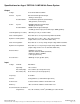
Power System Manual CXPS 48-1.8-M2, 48V Pos Gnd Power System 053-991-B0 Drawing List: The following drawings are included in this manual to provide the necessary information required for routine operation and fault diagnosis of the system.
MANUAL ADDENDUM Unit Description: Power System Manual, CXPS 48-1.8-M2, 48V Pos Gnd Document Affected P/N: 053-991-B0 Revision: B # 1 Date 09-11-09 Page# 2 Line# 9 Correction to be implemented Add text: Also available: CXPS configuration with AC input terminal block modification to feed two modules via each side of shelf. 6 Add text: CXPS configuration with AC input terminal block modification (bulk feed to two modules per side of shelf).................. Part Number (TBA) 35 Add sub-section 5.3.
Specifications for Argus’ CXPS 48-1.8-M2 48Vdc Power System Output Voltage: Current: Power: 42 to 58Vdc within rated limits System: 262.5A maximum @ nominal input ~168A @ 115Vac input Rectifier Module: 37.
Specifications for Argus Technologies’ CXPS 48-1.8-M2 48Vdc Power System Continued Connections Load Connections: AM breakers (1-pole): 1/4” holes on 5/8” centers AM breakers (multiple pole): 3/8” holes on 1” centers (with adapter) Battery Terminations: AM breakers (1-pole): 1/4” holes on 5/8” centers AM breakers (multiple pole): 3/8” holes on 1” centers (with adapter) Alarm/Signal Connections: 0.14mm2 to 1.50mm2 (#26 to #16 AWG) AC Input: Terminal blocks 2.
Specifications for Argus Technologies’ CXPS 48-1.8-M2 48Vdc Power System Continued Safety NOTE: Safety certifications performed at rectifier level only. EN 60950: Rectifier output shall be rated SELV suitable for connection to TNV-1 circuits UL: 60950 CSA: C22.2 No.
MANUAL ADDENDUM Unit Description: Power System Manual, CXPS 48-1.8-M2, 48V Pos Gnd Document Affected P/N: 053-991-C0 Revision: A # 1 Date 08-11-18 Page# 2 of 053-991-C0 Line# 43 Correction to be implemented Add list option for 018-573-20 (CXCM2): Auxiliary Power Input ..................................................... List 101 MANUAL ADDENDUM Authorized by: FORM 954-010-10 053991c0a1_addendum_CXCM2.
Specifications for Argus’ CXCM2 Cordex Controller Modular 2RU Model Basic Unit, CXCM2 Input Voltage: 17 to 65Vdc within rated limits Current: <100mA @ 48Vdc <200mA @ 24Vdc MTBF: >430,000 hours @ 30°C (86°F) EMC: The unit meets requirements of: ICES-003 Class B EN 55022 Class B (CISPR 22) EN 61000-4-2 ESD EN 61000-4-3 Radiated Immunity EN 61000-4-4 EFT /Burst EN 61000-4-6 Conducted Immunity FCC Part 15 Class B, FCC Part 68 In accordance with FCC requirements, we provide the following statement as spe
Specifications for Argus’ CXCM2 Cordex Controller Modular 2RU Model Continued Hardware Specifications, CXCM2 CPU: Coldfire RAM: 8MB Flash: 4MB standard, 8MB optional Display: 160 x 160 pixel grayscale LCD Front Panel Controls: Reset button and touch panel (display and input device) LED’s: System OK (Green) Power System Minor Alarm (Yellow) Power System Major Alarm / Controller Fail (Red) Audio: Built-in speaker for alarm and popup message tones Dimensions: 86mm H x 128mm W x 255mm D (3.
IMPORTANT SAFETY INSTRUCTIONS SAVE THESE INSTRUCTIONS This section contains important instructions that should be followed during the installation and maintenance of equipment and batteries. Please read all of the instructions before operating the equipment, and save this manual for future reference. A licensed electrician MUST perform connections to the branch circuit of service feed.
Electrical Safety WARNING Hazardous voltages are present at the input of a power system. The DC output from rectifiers and batteries, though not dangerous in voltage, has a high short-circuit current capacity that may cause severe burns and electrical arcing. Before working with any live battery or power system, follow these precautions: • • • Remove all metallic jewelry; e.g., watches, rings, metal rimmed glasses, necklaces.
TABLE OF CONTENTS 1 INTRODUCTION ............................................................................................................................................................. 1 1.1 1.2 1.3 1.4 2 FEATURES ................................................................................................................................................................... 3 2.1 2.2 2.3 2.4 3 Check System Connections...............................................................................
8.1 8.2 8.3 9 Fan Replacement........................................................................................................................................ 26 MOV Replacement...................................................................................................................................... 26 CXCM2 Replacement (as used with 1.8kW shelf) ...................................................................................... 27 ARGUS CONVENTIONS ...................................
1 Introduction 1.1 Scope of the Manual This instruction manual covers the features and installation of Argus Technologies’ CXPS 48-1.8-M2 48V Power System. NOTE: To aid the user with installation, frequent reference is made to drawings located at the rear of this manual. 1.2 Product Overview The CXPS 48-1.8-M2 is a complete integrated 48Vdc power system with 262.5A capacity. The system utilizes the advanced Cordex CXCM2 controller and 48V 1.8kW rectifier modules.
1.3 System Configurations The system is available to order in the following configurations: Description Part Number CXPS 48-1.8-M2, Cordex base 48V power system, 19/23” rail mount ............................................. 053-991-20-000 CXPS 48-1.8-M2 system installed in 7foot Z4 23” rack with 2x battery trays.................................... 053-991-20-040 CXPS 48-1.8-M2 system installed in 7foot Z4 19” rack with 3x battery trays.................................... 053-991-20-031 1.
2 Features 2.1 System Overview The basic system configuration is called out by Argus part number 053-991-20-000; which includes: • • • • • • • • 300A DCP03 distribution center Cordex 2RU Modular System Controller (CXCM2) Two (2) Cordex 48-1.8kW 4-module rectifier shelves (7x total rectifier positions available) Kydex rear cover 19” rack mount rails (center and flush mount) 19” to 23” rack mount adaptors System integration cabling and bus work Two (2) battery temperature compensation probes (12’ each).
2.2.3 Shunt A 400A shunt is included, in the CXPS 48-1.8-M2 system, for system current measurement. The shunt is installed in series with the batteries and the system controller automatically calculates load current. 2.2.4 Internal Alarm Card The DCP03 includes a standard alarm card providing a common interface point to internal system I/O connections, an LVD override switch, and LED indication of breaker trip.
2.3 CXCM2 Features The controller is mounted in the rectifier system shelf and brings advanced monitoring technology to the Cordex series of rectifiers.
2.3.2 LEDs The CXC has three LEDs located on the front panel. These are used to display the alarm status of the power system, CXC progress and status during startup, and file transfers. 2.3.2.1 Alarm Conditions The CXC illuminates the LED that corresponds to the system alarm status. The following show the corresponding alarm status for each LED color: Green – OK, no alarms present Yellow – Minor alarm is present (no major alarms) Red – Major alarm is present.
2.3.7 Alarm and Control Output Relays The CXC contains Form C digital alarm output relays to extend alarms and control external apparatus. Each internally generated alarm or control signal may be mapped to any one of the relays, or, several signals may be mapped to just one relay or none at all. 2.3.8 Network Connection and Remote Communications The Cordex system can be set up, monitored and tested via Ethernet 10/100 Base-T serial data connection. The communication protocol supports a web interface.
The LED will flash (~2Hz), when a minor alarm is detected, if the modules output capability has been reduced or a minor component failure is detected during the following conditions: VAC meter fail Fan fail Current limit (programmable option) Temperature sense fail AC foldback Low output voltage Power limit (programmable option) Soft start operation Remote equalize High output voltage High temperature foldback Communications lost. The LED remains off in the absence of an alarm.
2.4.6 Over Temperature Protection Each rectifier module is protected in the event of an excessive increase in temperature due to component failure or cooling airflow blockage. During over temperature conditions, the rectifier limits the output power as well as the output current. If temperature continues to increase, a shutdown of the rectifier is initiated. The rectifier shall restart automatically if the temperature has returned to a safe level. 2.4.
limiting can be used to mate the rectifier output current ampacity to the needs of the load and parallel battery to minimize excessive battery recharge current. The rectifier will sustain a short circuit at the output terminals indefinitely. The maximum short circuit current shall not exceed 105% of the rated full load current. 2.4.12 Power Limiting Each rectifier module is designed to limit power output to the module specification.
3 Inspection 3.1 Packing Materials All Argus products are shipped in rugged, double walled boxes and suspended via solid inserts to minimize shock that may occur during transportation. Packaging assemblies and methods are tested to International Safe Transit Association standards. Power systems are custom packaged in heavy-duty plywood crates. Products are also packaged with Cortex. This plastic wrap contains a corrosive-inhibitor that protects the product from corrosion for up to two years.
4 Installation This chapter is provided for qualified personnel to install and interconnect the power components within the Argus power system. Regarding battery installation, refer primarily to the manufacturer’s guidelines for more specific information. NOTE: To aid the user with installation, frequent reference is made to drawings located at the rear of this manual. 4.1 Safety Precautions Refer to the Important Safety Instructions near the front of this manual. 4.
4.3 Power System Assembly and Mounting The power system must be mounted in a clean and dry environment. Sufficient free space must be provided at the front and rear of the power system. This is to meet the cooling requirements of the rectifiers utilized in the power system and to allow easy access to the power system components. NOTE: The DCP03 requires at least 1RU (1.75”) of space above the unit for tooling access to the load breaker ground connections.
4.7 Battery Installation This information is provided as a guideline and is not meant to imply that batteries are part of this power system. WARNING Follow battery manufacturer’s safety recommendations when working around battery systems and review the safety instructions provided in this manual. 4.7.1 Preparation/Mounting Batteries should be located in a temperature-controlled environment. The temperature should be regulated at approx. 25°C (77°F).
After assembly, batteries should be numbered and “as received” readings taken, including specific gravity, cell voltage and temperature. One cell will be designated as the pilot cell; this is usually the cell with either the lowest specific gravity or voltage. Refer to manufacturer's literature for guidelines.
5 Wiring This chapter provides cabling details and notes on cable sizing for DC applications with respect to the product. WARNING Ensure that power is removed by turning off rectifiers and removing battery line fuse or connection before attempting work on the wiring connections. Use a voltmeter to verify the absence of voltage. Clearly mark the correct polarity of the battery leads before commencing work on DC connections.
5.4 Calculating Output Wire Size Requirements Wire size is calculated by first determining the appropriate maximum voltage drop requirement. Using the formula below calculate the CMA wire size requirement. Determine the size and number of conductors required to satisfy the CMA requirement. CMA = (A x LF x K) / AVD, where: CMA = Cross section of wire in circular MIL area A = Ultimate drain in amps LF = Conductor loop feet K = 11.
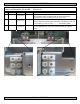
DCP03 input bar (hot) DCP03 input bar (return) Figure 9–Rear view of DCP03 distribution panel 5.6.2 Distribution Cabling Refer to guidelines supplied with the load equipment. Typically distribution cables are sized to provide a 0.5V loop drop at full load as well as meeting ampacity requirements of the protection fuse or circuit breaker. Distribution cabling must be terminated with 1/4”–5/8”C lugs for connecting to DCP03. 5.6.
5.7 Alarm Connections NOTE: To aid the user with installation, frequent reference is made to drawings located at the rear of this manual. Custom configurations may be detailed within the Argus power system documentation package. For terminal block connections, the recommended wire sizes are 0.14 to 1.50mm2 (#26 to #16 AWG) for the temperature range of 0 to 50 deg. C (as per UL/CSA). CAUTION: to reduce risk of fire, use only 0.14mm2 (#26 AWG) or larger wire.
5.10 Signal Wiring Connections for CXCM2 NOTE: To aid the user with installation, frequent reference is made to drawings located at the rear of this manual. Custom configurations may be detailed within the Argus power system documentation package. For terminal block connections, the recommended wire sizes are 0.14 to 1.50mm2 (#26 to #16 AWG) for the temperature range of 0 to 50 deg. C (as per UL/CSA). CAUTION: to reduce risk of fire, use only 0.14mm2 (#26 AWG) or larger wire. 5.10.
5.10.2.2 Programming the Digital Input The digital input channels can be programmed for “active high” or “active low.” Active high indicates “alarm on the presence of a ground signal” and active low indicates “alarm on the removal of a ground signal.” See CXC Software manual for detailed instruction on programming.
6 System Startup Visually inspect the installation thoroughly. After completing the system installation and power system wiring, perform the following startup and test procedure to ensure proper operation: 6.1 Check System Connections • • 6.2 Verify AC and Power the Rectifier Shelf • • • • 6.3 Install one power module. Verify AC input voltage is correct and turn on the corresponding feeder breaker. The power module OK LED should illuminate after a preset start delay.
6.4 CXCM2 Reset CAUTION Before removing a CXCM2 from a live system, or performing controller maintenance, an external LVD inhibit (or override) is required to avoid a disruption of service. See Section 6.5. 6.4.1 Soft Reset The reset button, located on the front panel of the optional CXCM2, is for restarting the microprocessor. When pressed momentarily, the unit beeps twice then resets.
7 Operation 7.1 Main Rectifier States Rectifier operation can be broken up into five main states: 1. 2. 3. 4. 5. Off, Start delay, Soft start, Normal operation, Turning off. Each state is characterized as being distinct and necessary for the operation of the rectifier. These states are briefly described below. 7.1.1 Off State The rectifier will be in the Off state immediately after power is applied to the rectifier or after a rectifier shutdown.
7.2.1 Output Voltage Modes Voltage modes can be thought of as modes that, under software control, can directly adjust the output voltage. The qualification of ‘under software control’ is made because there are processes that occur in the rectifier that can change the output voltage that do not adjust the output voltage directly (such as the rectifier being in current limit).
8 Maintenance Although very little maintenance is required with Argus systems, routine checks and adjustments are recommended to ensure optimum system performance. Qualified service personnel should do repairs. The following table lists a few maintenance procedures for this system. These procedures should be performed at least once a year. WARNING: HIGH VOLTAGE AND SHOCK HAZARD. Use extreme care when working inside the shelf while the system is energized. Do not make contact with live components or parts.
8.3 CXCM2 Replacement (as used with 1.8kW shelf) Refer to all safety instructions provided in the documentation package provided with your system. WARNING: HIGH VOLTAGE AND SHOCK HAZARD. Use extreme care when working inside the shelf while the system is energized. Do not make contact with live components or parts. Circuit cards, including RAM chips, can be damaged by static electricity. Always wear a grounded wrist strap when handling or installing circuit cards. 1.
9 Argus Conventions 9.1 Numbering System Argus Technologies uses an eight-digit drawing number system, which is broken into three blocks. The first three digits describe the category of the product; e.g., rectifier or fuse panel. The next three digits indicate the sequence in which the product number was allocated in a particular category.
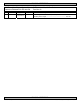
5(9,6,216 '(6&5,37,21 ':1 /75 '$7( $33' 5$&. 5$&.
)5217 9,(: 6,'( 9,(: 5 7<3 &;36 P 6<67(0 ,167$//(' ,1 IW = 5$&.
)5217 9,(: 6,'( 9,(: 5 7<3 &;36 P 6<67(0 ,167$//(' ,1 IW = 5$&.
5(9,6,216 '(6&5,37,21 ':1 /75 '$7( $33' &+$66,6 *5281' 678' %27+ 6,'(6 %5($.(5 2873876 +$5':$5( 21 &(17(56 6,7( *5281' &$%/( &211(&7,21 +$5':$5( 21 &(17(56 %5($.
)250 & 5(/$< $/$50 &86720(5 &211(&7,216 ',*,7$/ ,13876 &86720(5 &211(&7,216 86(' ,17(51$//< 127( $// 27+(5 ,13876 86(' ,17(51$//< /9' 29(55,'( 6:7,&+ *5((1 /9' $872 &21752/ /(' &;&0 ,17(5)$&( 3&% <(//2: /9' 29(55,'( /(' 86(' ,17(51$//< *(1(5$/ 385326( ,1387 &86720(5 &211(&7,216 /9' 29(55,'( ',675,%87,21 $/$50 3&% 3&% '(7$,/6 7+(6( '(6,*16 $1' 63(&,),&$7,216 $5( 7+( 3523(57< 2) $5*86 7(&+12/2*,(6 $1' 6+$// 127 %( &23,(' 25 86(' )25 0$18)$&785,1* :,7+287 ,76 :5,77(1 &216(17 8
1(*$7,9( 287387 %$5 326,7,9( 287387 %$5 / / / 1 / 1 / / / 1 / 1 $& ,1387 )(('6 02'8/(6 [ +(; %2/76 $1' :$6+(56 6833/,(' [ +(; %2/76 $1' :$6+(56 6833/,(' $& ,1387 )(('6 02'8/(6 5($5 9,(: &$1 ,1 5- 2))6(7 - &$1&20 &$1 + 127 &211(&7(' &$1 / 127 &211(&7(' 127 &211(&7(' &211(&7,21 '(7$,/6 - &$1 287 5- 2))6(7 - 5,*+7 6,'( 9,(: - &$1&20 &$1 + 127 &211(&7(' &$1 / 127 &211(&7(' 127
This page intentionally left blank.
WARRANTY AND SERVICE INFORMATION Technical Support Technical support staff are available for answering general questions related to installation, operation and maintenance of Argus products. In Canada and the USA, call Argus toll free at +1-888-GO-ARGUS (+1-888-462-7487) 7:30 am to 5:00 pm Pacific Standard Time. For emergencies, call +1-888-GO-ARGUS (+1-888-462-7487) 24 hours a day, seven days a week. Customers outside Canada and the USA, call +1-604-436-5547 for technical support.
Service Centers Factory Service Centers Canada and International Argus Technologies Ltd. ATTN: RMA Returns 7033 Antrim Avenue Burnaby, BC, V5J 4M5 Canada Tel: +1 604 436 5900 Fax: +1 604 436 1233 Email: returns@argusdcpower.com USA Argus Technologies Inc. ATTN: RMA Returns 3116 Mercer Avenue Bellingham, WA, 98225 USA Tel: +1-360 756 4904 Fax: +1-360 647 0498 Email: returns-usa@argusdcpower.com Asia-Pacific PCM Electronics (Dong Guan) Co., Ltd.
This page intentionally left blank.