AlphaNet™ DSM3 Series DOCSIS® Status Monitor for the XM3 CableUPS® Technical Manual Effective: March 2014
Safety Notes Review the drawings and illustrations contained in this manual before proceeding. If there are any questions regarding the safe installation or operation of the system, contact Alpha Technologies or the nearest Alpha representative. Save this document for future reference. To reduce the risk of injury or death and to ensure the continued safe operation of this product, the following symbols have been placed throughout this manual. Where these symbols appear, use extra care and attention.
AlphaNetTM DSM3 Series DOCSIS® Status Monitor for XM3-HP CableUPS® 745-814-B11-001, Rev. C Effective Date: March 2014 © 2014 by Alpha Technologies, Inc. Disclaimer Images contained in this manual are for illustrative purposes only. These images may not match your installation. Operator is cautioned to review the drawings and illustrations contained in this manual before proceeding.
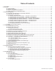
Table of Contents 1.0 Introduction .......................................................................................................................................................................8 2.0 Overview .....................................................................................................................................................................10 2.1 System Diagram.............................................................................................................
Table of Contents, continued 7.0 Installation .....................................................................................................................................................................64 7.1 Verifying Power Supply Device Address ............................................................................................................64 7.2 Installation / Replacement Procedure in XM3 Power Supplies..........................................................................65 7.
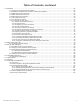
Figures & Tables Fig. 1-1, AlphaNet DSM3x ......................................................................................................................................................8 Fig. 1-2, AlphaNet DSM3 ........................................................................................................................................................8 Fig. 1-3, AlphaNet DPM .....................................................................................................................
Figures & Tables, continued Fig. 9-1, XM3 Smart Display Screens ..................................................................................................................................80 Fig. 9-2, Communications Section - General Page ..............................................................................................................81 Fig. 9-3, Power Supply Section - General Page ............................................................................................................
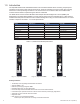
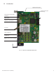
1.0 Introduction The AlphaNet DSM3 Series Embedded DOCSIS Communications Module allows monitoring of Alpha power supplies through existing cable network infrastructure. Advanced networking services provide quick reporting and access to critical powering information. This manual focuses on the three models of the DSM3 Series Communications Module complementing the XM3-HP CableUPS.
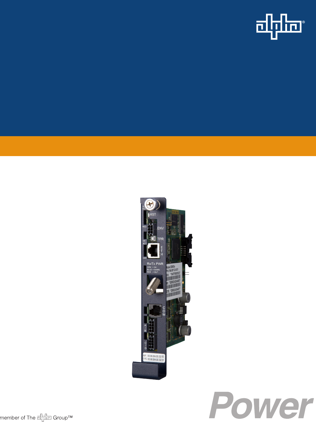
1.0 Introduction Intelligent CableUPS Interface (located on other side of the board) Single Microcontroller Cable Modem Design Environmental IO Connector (DSM3X and DPM only) Tamper Connector Ethernet Port for Local Diagnostics RF Connector COM Port (DSM3X only) Battery Monitoring Connection A/B (DSM3 and DSM3X only) Battery Monitoring Connection C/D (DSM3X only) Fig. 1-4, Side view, AlphaNet DSM3 Series 745-814-B11-001, Rev.
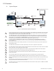
2.0 Overview 2.1 System Diagram 10 SNMP-based Network Management System 2 DSM3 Series 1 Power Supply 5 Coax/HFC Network 6 CMTS 12 TCP/IP Network 4 Local Computer 3 External Generator 7 DHCP Server 8 TFTP Server 9 TOD Server 11 Web Browser Fig. 2-1, Representative System Arrangement 10 1 All power supply data is stored in the power supply Inverter Module's class information base (CIB) tables in the power supply.
2.0 Overview 2.2 Network Connectivity The DSM3 Series cable modem must be recognized by the CMTS as a valid device to be assigned an IP address from the DHCP server, to locate the TFTP and TOD servers and to communicate with the SNMP management server (trap receiver). Data from both the cable modem and power supply are accessed and managed through the modem’s IP address on the secure private modem network.
2.0 Overview DSM3 Series Start Up and Reboot Routine TCP/IP Network 2.4 TFTP Server 5 Network Management System TOD Server 4 MIB Browser DHCP Server 3 Web Browser Switches Routers Firewalls HFC Network CMTS 2 6 DSM3 Series 1 Power Supply 7 Local Laptop The above diagram, read left to right, indicates the order of operations as the Communications Module comes online. There are certain conditions that must exist for each step to occur, resulting in successful data monitoring and management.
3.0 Network Configuration 3.1 Provisioning the DHCP Server with the MAC Addresses On the DHCP server, assign the cable modem’s CM MAC address with a DOCSIS Configuration File to set modem communication options. (See Section 3.3, The DOCSIS Configuration File for instructions on how to create a DOCSIS Configuration File). The CM and CPE MAC addresses are located in two places on the DSM3 Series and on the packing slip, see below.
3.0 Network Configuration 3.2 Establishing IP Connectivity The DSM3 Series supports the CableLabs DOCSIS 2.0+IPv6 implementation. The main benefit of IPv6 is its expanded addressing capability, increasing the address space from 32 to 128 bits, providing virtually unlimited number of networks and systems. The DSM3 Series determines the IP provisioning mode via the CableLabs SNMP MIB parameter docsIf3CmMdCfgIpProvMode (SNMP OID: 1.3.6.1.4.1 .4491.2.1.20.1.31.1.1).
3.0 Network Configuration 3.3 The DOCSIS Configuration File 3.3.2 Setting Modem Community Strings — DOCSIS 2.0+IPv6 Method Set the modem community strings with the DOCSIS Configuration File for a IPv6 network by including the following SNMP parameters: TLV Type TLV Parameter Description Value 53 SNMPv1v2c Coexistence Configuration This object specifies the SNMPv1v2c Coexistence Access Control configuration of the CM. This TLV creates entries in SNMPv3 tables as specified in [DOCSIS OSSIv3.
3.0 Network Configuration 3.3.4 Setting SNMP Trap Destination Addresses — DOCSIS 2.0+IPv6 Method Set the SNMP Trap Destination Addresses via the DOCSIS Configuration File by including the following SNMP parameters: TLV Type TLV Parameter Description Value 38 SNMPv3 Notification Receiver This config file element specifies a Network Management Station that will receive notifications from the modem when it is in Coexistence mode. Up to 10 of these elements may be included in the configuration file.
3.0 Network Configuration 3.3.5 Sample DOCSIS Configuration File Entries — DOCSIS 2.0 (IPv4) A SNMP MIB Object (11) [Len=21]:docsDevNmAccessStatus.1/4 SNMP MIB Object (11) [Len=21]:docsDevNmAccesslp.1/10.56.21.0 SNMP MIB Object (11) [Len=21]:docsDevNmAccesslpMask.1/255.255.255.0 SNMP MIB Object (11) [Len=25]:docsDevNmAccessCommunity.1/"RW STRING" SNMP MIB Object (11) [Len=25]:docsDevNmAccessInterfaces.1/"@" SNMP MIB Object (11) [Len=21]:docsDevNmAccessControl.
3.0 Network Configuration 3.3 The DOCSIS Configuration File 3.3.6 Sample DOCSIS Configuration File Entries — DOCSIS 2.0+IPv6 A B SNMPv1v2c Coexistence Configuration SNMPv1v2c Community Name:ReadWrite SNMPv1v2c Transport Address Access SNMPv1v2c Transport Address:0.0.0.0/0 SNMPv1v2c Transport Address Mask:0.0.0.
3.0 Network Configuration 3.3 The DOCSIS Configuration File 3.3.7 Proprietary Configuration File ‘atidoc03.cfg’ The DSM3 Series will attempt to download a TLV-formatted file ‘atidoc03.cfg’ from the modem’s provisioning TFTP server at start up and every 24 hours thereafter. The atidoc03.
3.0 Network Configuration 3.4 Setting Communication Options Communications Settings may be changed through the Alpha MIB remotely using an SNMP MIB browser or automatically by placing the SNMP parameters into the DOCSIS Configuration File. See Section 6.0, Data Management for an explanation of the Alpha MIB. NOTE: Before setting options, verify UDP ports 37, 69, 161, 162 and TCP port 80 are not blocked. SNMP Parameter Type Description Value atiMgmtSnmpTrapOnNormal OID: 1.3.6.1.4.1.926.1.3.1.5.1.
4.0 Web Interface Overview The DSM3 Series Communications Module provides an embedded Web server interface to allow operations personnel the ability to connect locally or remotely via TCP/IP over Ethernet with a laptop/computer to verify the status of common data points and to configure various operating parameters. 4.
4.0 Web Interface 4.1 Local Web Server Access NOTE: If you are unable to view the home page of the DSM3 Series using IP address 192.168.100.1, the network configuration on the computer that is being used to connect to the DSM3 Series Communications Module may require a temporary static IP address (192.168.100.2) to be configured. Use the following procedure to configure a static IP address on a laptop or computer with the Windows XP operating system: 1.
4.0 Web Interface 4.1 Local Web Server Access Use the following procedure to configure a static IP address on a laptop or computer with the Windows 7 operating system: 1. Click the Start button (lower left button on most Windows® computers). 2. When the window pops up, click Control Panel (usually about half the way down the second column). 3. Click Network and Sharing Center. 4. Click Local Area Connection. 5. Click the Properties button. 6. You will see a dialog box much like Fig.
4.0 Web Interface 4.2 Remote Web Server Access To remotely access the DSM3 Series Communications Module Web server utilizing a Web browser, use the following procedure: NOTE: For Web server (HTTP) access, port 80 must not be blocked. 1. Connect the laptop or computer’s network interface port to the company’s Ethernet network. 2. Open a Web browser. 3. Enter the DSM3 Series' DHCP designated IP address (e.g., 192.168.1.124) into the Web browser’s address field.
4.0 Web Interface 4.3 Navigating the Web Page Once the Web page has been successfully accessed, the operator is able to select a link on the header bar and the page specific to the topic will open enabling real-time data to be observed. See Fig. 4-7 for DSM3 Series navigation bar items.
4.0 Web Interface 4.3.1 Web Interface Security Levels The DSM3 Series Communications Module has two levels of function-specific security. General operations are Level 1. Configuration-related functions are Level 2. Refer to Table 4-1 for default User Name and Security Passwords. DSM3 Series Web Page Security OID Function Value 1.3.6.1.4.1.4413.2.2.2.1.1.3.3.0 Level 1 User Name Alpha 1.3.6.1.4.1.4413.2.2.2.1.1.3.4.0 Level 1 Security Password AlphaGet 1.3.6.1.4.1.4413.2.2.2.1.1.3.1.
4.0 Web Interface 4.4 Verifying Communication Parameters Click the General menu of the web page to display common communication settings and values. Click the Advanced Communication menu to view additional communication parameters. Fig. 4-8, Communication Parameters (data values shown for illustration purposes only) Fig. 4-9, Advanced Communication Parameters (data values shown for illustration purposes only) 745-814-B11-001, Rev.
4.0 Web Interface 4.5 Verifying Power Supply and Battery Parameters Click the General menu to access Power Supply and individual battery voltage values. Important parameters such as current alarm status, inverter status and tamper status can be quickly verified on this page. Additional power supply parameters can be viewed and configured on the Power Supply page located in the Advanced Configuration menu. Fig. 4-10, Power Supply and Battery Parameters (data values shown for illustration purposes only) 4.
4.0 Web Interface 4.7 Viewing HMS Alarm Status via the Web Page HMS alarms levels and current states may be viewed by clicking on the HMS Alarms link on the Advanced Configuration menu (see Figure 4-12). Parameter values cannot be edited on this Web page. An SNMP MIB browser or status monitoring software may be used for such edits. Alarms settings may be exported by selecting the Export button at the bottom of the page. Alarms settings may be distributed to other DSM3 Series units.
4.0 Web Interface 4.8 Setting the I/O Controller via the Web Page Access the I/O Environment page in the Advanced Configuration menu to adjust the settings for the Tamper Switch and I/O Controller. The Tamper Switch polarity may be changed by clicking on the preferred tamper switch polarity button. The I/O Controller section provides a user interface to select the type of device that will be connected and monitored via the ENV connector of the Communications Module.
4.0 Web Interface 4.9 Viewing and Configuring Power Supply settings via the Web Page Click the Advanced Configuration menu and select Power Supplies to view connected power supply parameters. The power supply parameters with a formatted text box or a menu around the value can be configured. Click the Start Test button to remotely initiate power supply tests. When prompted, refer to Section 4.3.1, Web Interface Security Levels for the applicable User Name and Security Password. Fig.
4.0 Web Interface 4.9 Viewing and Configuring Power Supply settings via the Web Page Fig. 4-14, Advanced Power Supply Settings Screen, continued (data values shown for illustration purposes only) NOTE: When the Battery Model is set to "Other", the battery charging parameters such as charger voltages, battery capacity, and temperature compensation can be customized, otherwise default values are populated for Alpha supported batteries.
4.0 Web Interface 4.10 Viewing and Configuring Generator Settings via the Web Page When a generator is connected to a DSM3x, the generator page listed in the Advanced Configuration menu will populate a list of the various parameters and alarm statuses. Generator Self Tests may be remotely started by clicking on the Start Test button. When prompted, refer to Section 4.3.1, Web Interface Security Levels for User Name and Security Password. Fig.
4.0 Web Interface 4.11 Tools Menu – Constellation and Microreflections The Web Page of the DSM3 Series Communications Modules provides some basic tools for analyzing impairments on the DOCSIS network. The “Tools” menu selection on the Web page provides access to both the Constellation and Microreflections pages. Note: The Constellation and Microreflections tools provided on the DSM3 Series Web page are for basic identification of common network impairments.
4.0 Web Interface 4.11.1 QAM Constellation Tool The tables on the right hand side of the screen provide a summary of common parameters associated with QAM Constellation analysis. Here’s a breakdown of the parameters listed: • Frequency - Downstream frequency given in MHz. • Power – Downstream power given in dBmV. • Modulation – Modulation type associated with the downstream channel. • Lock Status – Current cable modem connectivity state.
4.0 Web Interface 4.11.2 QAM Constellation Common Impairments, continued Individual cells and entire QAM constellation Fig. 4-18, Fuzzy (Low CNR and/or Low MER) and Individual Cell Characteristics Individual cells and entire QAM constellation Fig. 4-19, Doughnuts (Coherent Interference) and Individual Cell Characteristics 36 745-814-B11-001, Rev.
4.0 Web Interface 4.11.2 QAM Constellation Common Impairments, continued Individual cells and entire QAM constellation Fig. 4-20, Gaussian Noise and Individual Cell Characteristics Entire QAM constellation Fig. 4-21, Rectangular vs. Square (I-Q Imbalance) and Entire Constellation Shape 745-814-B11-001, Rev.
4.0 Web Interface 4.11.2 QAM Constellation Common Impairments, continued Entire QAM constellation Fig. 4-22, Corners Squeezed to Center (Gain Compression) and Entire Constellation Shape Entire QAM constellation Fig. 4-23, Circular Smear (Phase Noise) and Entire Constellation Shape 38 745-814-B11-001, Rev.
4.0 Web Interface 4.11.2 QAM Constellation Common Impairments, continued Entire QAM constellation Fig. 4-24, Twisted or Skewed (Quadrature Distortion) and Entire Constellation Shape 4.11.3 Microreflections Tool The Microreflections page provides details about impairments on the DOCSIS network and the approximate distance(s) of the impairment(s). In order to provide the analysis and a display of possible impairments, this tool requires the Adaptive Equalization function to be enabled on the CMTS.
4.0 Web Interface 4.12 Viewing AlphaApps Information via the Web Page The status of the optional AlphaApps Card may be viewed by navigating to the AlphaApps selection on the Apps menu of the DSM3 Series Web page. Status and firmware version are typical parameters listed for this installed component of the power supply. A Configure/Save button is available for manually setting the Application Clock. Refer to Section 4.3.1, Web Interface Security Levels for User Name and Security Password.
4.0 Web Interface 4.13 Battery Management Technician ID, battery conductance measurements, battery model and battery manufacturing dates can be manually entered via the Web page interface. Navigate to the Battery Management selection on the Apps menu Web page to access the battery management details. A Configure/Cancel/Save button is available for the configurable settings on this page. Click the Configure button to enable the configuration/editing mode, then click the Save button to save all the edits.
4.0 Web Interface 4.13 Battery Management, continued Click the drop down menu to view a selection of common battery models. If the installed battery model is not listed for your particular configuration, then select Other for the model type. Click the Save button to save all edits. Fig. 4-28, Battery Model Selection 42 745-814-B11-001, Rev.
4.0 Web Interface 4.14 Viewing Power Supply Event and Configuration Logs Navigate to the History menu for viewing the power supply event and configuration logs. The System Logs provides a snapshot of the five most recent entries of the power supply event log and the power supply configuration log. For a more comprehensive list, click on the link or select from the History menu for the desired log file. Fig. 4-29, DSM3 System Log 745-814-B11-001, Rev.
4.0 Web Interface 4.14 Viewing Power Supply Event and Configuration Logs, continued A Time Offset selection is available on each log table for selection of your current time offset from Greenwich Mean Time (GMT). Select the time offset that best matches your location to enable the local time in the log tables. Refer to Table 4-2 for a list of time zone offsets and relative locations. GMT Offset Location Reference +12 Auckland +11 Magadan +10 Sydney +9.
4.0 Web Interface 4.14 Viewing Power Supply Event and Configuration Logs, continued The Power Supply event log records events that occur in the normal course of daily power supply operation such as IP address changes, inverter health, alarms, power outages, etc. A Time Offset selection can be configured to display the events in the specified time zone. The event log data may be downloaded by clicking on the Download CSV (comma-separated values) button located at the bottom left of the page.
4.0 Web Interface 4.14 Viewing Power Supply Event and Configuration Logs, continued The Power Supply Configuration Log, accessible via the History drop down menu, contains events that occur infrequently or only once, such as Communications Module configuration (firmware version), CM MAC address, Inverter Module serial number, etc. The configuration log data may be downloaded by clicking on the Download CSV button. The Configuration Log will store a maximum of 255 entries. Fig.
4.0 Web Interface 4.15 Battery Event Log The Battery Event Log can be accessed by navigating to the History menu. The Battery Event Log records the battery conductance measurements and battery manufacturing dates. Download the Battery Event Log data by clicking the Download CSV button. The Battery Event Log will store a maximum of 1024 entries, then it will automatically roll over. Fig. 4-32, Battery Event Log 4.
5.0 Upgrading Firmware 5.1 Upgrading DSM3 Series Modem Firmware The firmware is upgraded using standard DOCSIS methods as defined in RFC4639. There are two ways to upgrade the modem’s firmware: By directly setting the appropriate MIB parameters in the docsDevSoftware branch, or by including the appropriate SNMP parameters and values in the modem’s DOCSIS Configuration File, stored in the TFTP root directory. Both methods are explained below. 5.1.
5.0 Upgrading Firmware 5.1.3 Upgrading Manually by Setting SNMP Parameters 1. Acquire the firmware and CVC files for your DSM3 Series from Alpha Technologies. 2. Import the CVC into the modem’s DOCSIS Configuration File (to create a Configuration File, see Section 3.3, The DOCSIS Configuration File). 3. Set the following MIB parameters using an SNMP MIB browser. For additional information regarding the SNMP MIB parameters, refer to the table in Section 5.1.2, Modem Firmware Upgrade SNMP Parameters.
6.0 Data Management 6.1 SCTE-HMS MIBs The DSM3 Series remotely reports power supply data and alarms using the Simple Network Management Protocol (SNMP) over the DOCSIS (Data Over Cable Service Interface Specification) communications standard. The DSM3 Series typically reports into a centralized Network Management System (NMS) through a standard collection of data access points referred to as the SCTE-HMS Management Information Bases (MIBs).
6.0 Data Management 6.2 SCTE-HMS MIB Alarms 6.2.1 SCTE-HMS Configurable Alarms The HMS discrete and analog alarms provide the capability to monitor and alarm various power supply and environmental conditions and measurements. The alarms in the SCTEHMS propertyTable and the discretePropertyTable can be defined and set to provide a custom monitoring system. The following section provides an example and detailed information on how to set values and enable or disable alarms in the MIB tables.
6.0 Data Management 6.2.1 SCTE-HMS Configurable Alarms, continued The following table displays the various analog alarms with common settings for the DSM3 Series Communications Module.
6.0 Data Management 6.2.
6.0 Data Management 6.2.1 SCTE-HMS Configurable Alarms, continued genMinorAlarm (2) The generator is indicating a minor alarm. The generator requires attention, but does not require an immediate visit to the site. discreteMinor genMajorAlarm (1) No Alarm Disable genMajorAlarm (2) The generator is indicating a major alarm. The generator requires immediate attention.
6.0 Data Management 6.2.1 SCTE-HMS Configurable Alarms, continued 3. Distribute the “AlarmSettings.acf” file to other DSM3s. The “AlarmSettings.acf” file is distributed to other DSM3s by setting the following Alpha MIB parameters to the indicated values. This can be done to an individual DSM3 using a MIB browser, or to multiple DSM3s by placing the SNMP OIDs into the modem’s DOCSIS configuration file or the proprietary atidoc03.cfg configuration file.
6.0 Data Management 6.2.2 SNMP Traps Use of SNMP Traps allow the network manager to set conditions (alarms) under which the device (or devices) autonomously reports to the headend the existence of the pre-configured event. The type of event determines the level of action to be taken. 1. Verify the IP address of the trap destination server(s) has been configured. If the trap destination server requires configuration, refer to Section 3.3.3 Setting SNMP Trap Destination—DOCSIS 2.0 (IPv4) Method, and 3.3.
6.0 Data Management 6.2.2 SNMP Alarm Traps, continued Varbind Explanation Binding #1 commonPhysAddress OID: 1.3.6.1.4.1.5591.1.3.2.7.0 MAC address of the Communications Module Binding #2 commonLogicalID OID: 1.3.6.1.4.1.5591.1.3.1.1.0 Optional user-configurable parameter that is often used to provide a unique logical name, or even the physical address of where the Communications Module is installed. Binding #3 alarmLogInformation OID: 1.3.6.1.4.1.5591.1.2.3.1.2.
6.0 Data Management 6.2.3 General Power Supply Alarms The Intelligent CableUPS detects a wide array of alarms and displays the type of active alarm in the Smart Display screen and the severity of alarm (e.g., Major/Minor) by means of the Inverter Module LEDs. General power supply alarms are passed directly from the power supply to the Communications Module without specific definition and are classified in the HMS MIB table as psMinorAlarm and psMajorAlarm.
6.0 Data Management 6.2.3 Active Alarm General Power Supply Alarms Alarm type Alarm Category Probable Cause of Alarm Corrective action Standby Disabled Self Test FAIL Major PWR Output voltage failed or batteries less than 1.85V/C during Self Test. 1. Check Batteries 2. Check Inverter NO LINE ISOLATION Major PWR Line isolation has failed and Inverter operations are suspended. 1.
6.0 Data Management 6.2.4 Battery Alarms The Intelligent CableUPS detects a wide array of battery alarms and displays the type of active alarm in the Smart Display screen and the severity of alarm (e.g., Major/Minor) by means of the Inverter Module LEDs. Active Alarm Alarm type Alarm Category Probable Cause of Alarm Corrective action NO BATTERIES Major LOW BATT VOLTS BATT Detected the absence of batteries (alarm inactive when battery capacity or number of battery strings is set to 0) 1.
6.0 Data Management 6.3 The Alpha MIBs Accompanying the release of the DSM3 Series are 21 new MIB files. These are backward-compatible with the existing Alpha Technologies DSM Series Communications Modules. These MIBs are available by contacting Alpha Technical Support. A complete listing is shown below: ATI-BB-SYS-APPS-MIB.my ATI-BB-SYS-LOGS-MIB.my ATI-BB-SYS-VIEW-MIB.my ATI-MANAGEMENT-MIB.my ATI-MGMT-SNMP-MIB.my ATI-MGMT-SYS-ACCESS-MIB.my ATI-MGMT-SYS-DOWNLOAD-MIB.my ATI-MGMT-SYS-GENRL-CTRL-MIB.
6.0 Data Management 6.3 The Alpha MIBs The Alpha MIB is defined within the enterprises branch of the MIB tree starting at 1.3.6.1.4.1.926 and is organized as shown in the overview below: MIB Tree ccit iso (1) org (1.3) dod (1.3.6) internet (1.3.6.1) directory (1.3.6.1.1) mgmt (1.3.6.1.2) experimental (1.3.6.1.3) private (1.3.6.1.4) enterprises (1.3.6.1.4.1) atl(1.3.6.1.4.1.926) alphaTechInc(1.3.6.1.4.1.926.1) atiLegacyReserved01(1.3.6.1.4.1.926.1.1) atiTables (1.3.6.1.4.1.926.1.2) atiManagement (1.3.6.1.4.
6.0 Data Management 6.3 The Alpha MIBs 6.3.1 The Alpha MIB Structure Measurements and settings for the power supply, generator, batteries and DSM are accessed using Simple Network Management Protocol (SNMP) through the Alpha Management Information Base (MIB) files. The Alpha MIB is defined within the enterprise branch of the MIB tree starting at 1.3.6.1.4.1.926 and is organized into the following branches: Alpha CIB Tables – atiTables (1.3.6.1.4.1.926.1.2.
7.0 Installation 7.1 Verifying Power Supply Device Address Before installing the hardware, provision the DHCP server with the cable modem’s CM MAC address. This allows the installation to be verified while the technician is on-site, eliminating the need for a second visit if there are problems with the installation. WARNING! To reduce the risk of electric shock, completely remove the Inverter Module from the power supply prior to installation.
7.0 Installation 7.2 Installation / Replacement Procedure in XM3 Power Supplies If the XM3 CableUPS has been shipped without a DSM3 Series module, or the existing module requires removal and replacement, do so via the the following procedure: 1. Switch OFF the Inverter Module battery breaker. NOTE: With the battery breaker in the OFF position, the power supply will not go into inverter mode. 2. Unplug all Inverter Module connections (e.g. battery cable, remote temperature sensor). 3.
7.0 Installation 7.2 Module Installation Procedure in XM3 Power Supplies Fig. 7-2, The 18-pin Connector 6. Line up the 18-pin mating connectors on the DSM3 Series and the XM3 Inverter Module. Gently push the DSM3 Series into the Inverter Module until the 18 pin mating connector is properly seated. Fig. 7-3, Connecting the Communications Module to the Inverter Module 7. Fasten the DSM3 Series to the Inverter Module by tightening the two captive screws.
7.0 Installation 7.
7.0 Installation 7.
7.0 Installation 7.
7.0 Installation 7.6 Connecting the RF Drop CAUTION! Install a grounded surge suppressor (Alpha P/N 162-028-10 or equivalent). Connect the RF drop according to the diagram below. The RF drop must have a properly installed ground block in the power supply enclosure. Recommended downstream RF level is 0 dBmV. Connect any other front panel connections at this time (e.g. battery strings, tamper switch). Grounded Surge Protector (See Caution Above) RF Cable to Headend Fig. 7-7, Connecting the RF Drop 7.
7.0 Installation 7.8 I/O Connections (TPR, ENV) The Alpha DSM3 series transponders (DSM3, DSM3x, DPM) are all populated with a Tamper interface to report the status of the power supply enclosure door when equipped with the optional tamper switch.
7.0 Installation 7.8.2 I/O Port Interface ENV Connector Pin Description 1 Logic Gnd 3 6 2 5V +/- 0.5V voltage Shotky Protection – 15mA max. – Relay current drive 2 5 3 Open/Close Control – 0V/15mA sink = Close, 3.
7.0 Installation 7.8.3 Configuring I/O Port Connections, continued atiMgmtSysIoSelect (1.3.6.1.4.1.926.1.3.2.8.1.0) MIB Value Device Reported Parameter or MIB Branch 1 No device (generic) I/O Pins Only 2 LAP Only atiMgmtSysIoLAPState 1.3.6.1.4.1.926.1.3.2.8.2.0 3 Heater Control Only atiMgmtSysTempMgr * 1.3.6.1.4.1.926.1.3.2.4 4 DC Generator Only atiMgmtSysIoGenState 1.3.6.1.4.1.926.1.3.2.8.3.
7.0 Installation 7.8.5 Connecting a Generic I/O Device The I/O cable P/N 875-627-25 is designed to monitor a single contact relay device through Pin 6 of the ENV connector. The I/O cable P/N 875-627-22 is designed to control a relay device through Env Pin 3 and also monitor a contact relay through Pin 4. For any other generic device configurations consult your Alpha representative. 7.8.6 Configuring and Monitoring a Generic I/O Device Set the parameter atiMgmtSysIoSelect 1.3.6.1.4.1.926.1.3.2.8.1.
7.0 Installation 7.8.8 Lightning Arrestor (LA-P-SM) Installation The physical installation of the LA-P-SM is shown below and consists of connecting the cable (Alpha p/n: 875-627-23) from the LA-P-SM's two leftmost screw terminals to the six pin ENV connector on the DSM3 Series or DPM and plugging the LA-P-SM into the enclosure‘s power outlet. 1. Insert cable into 3-pin connector 2. Tighten to .22 to .25N•m 3. Connect to LA-P-SM 4. Plug LA-P-SM into power outlet 5. Plug cable into ENV connector 7.8.
7.0 Installation 7.8.10 I/O Port: Heater Mat Control atiMgmtSysIoSelect = 3,5 NOTE: Heater control MIBs will continue to report regardless of atiMgmtSysIoSelect value, but DSM3x/DPM Web page will only display Heater Control status if atiMgmtSysIoSelect is set to “3” or “5.” A battery heater mat controller may be managed though the following set of parameters within the ‘atiMgmtSysTempMgr’ MIB branch. Parameter Access Values Description atiMgmtSysTempCtrl 1.3.6.1.4.1.926.1.3.2.4.1.
7.0 Installation 7.8.11 Connecting the Battery Heater Mat Controller, continued Once the connection has been made, Environmental Control Management can be configured using an SNMP MIB browser as indicated in the following tables. The Environmental Control MIB section begins at atiMgmtSysTempMgr (1.3.6.1.4.1.926.1.3.2.4). Status of the Environmental Control is also available via the Communications Module’s Web page by navigating to ‘Advanced Configuration’, ‘I/O – Environment’.
7.0 Installation 7.8.13 I/O Port: Emergency DC Generator (GEN) atiMgmtSysIoSelect = 4, 6 The DPM and DSM3x have the capability to report the status of the Alpha DCX Series Emergency DC Generator through the I/O or“ENV” port on the front of the Communications Module. See the DCX3000/DCX2000 Remote Status Monitoring (RSM) Assembly Kit Field Installation Guide, p/n 746-379-C0. 7.8.14 Configuring and Monitoring the DC Emergency Generator Set the parameter atiMgmtSysIoSelect 1.3.6.1.4.1.926.1.3.2.8.1.
8.0 Battery Sense Wire Kits 8.1 36V Single and Dual Strings Communications Module Battery Sense Wire Kits are required for individual battery voltage monitoring when the XM3 SAG option is not installed. For XM3 power supplies with the SAG option, it is recommended to use the specific SAG wire kits or the SAG adapter kits to accommodate any existing Communications Module Battery Sense Wire Kits.
9.0 Start Up and Verification 9.1 Initial Start Up and Local Verification To confirm successful hardware installation before leaving the installation site, verify network connectivity and correct hardware interconnection. To Verify Network Connectivity: The DS and REG LEDs on the front of the DSM3 Series should be ON solid green. This indicates successful registration with the headend.
9.0 Start Up and Verification, continued 9.0 Start Up and Verification 9.1 9.1 Up and Local Verification, continued InitialInitial StartStart Up and Local Verification, continued Connect a computer’s network port to the Communications Module’s Ethernet port using a Connect a computer’s network port to the Communications Module’s Ethernet port using a standard network cable. Launch an Internet browser and enter 192.168.100.1 into the address. The standard network cable. Launch Internet browser enter 192.
9.0 Start Up and Verification 9.2 Verifying Correct Hardware Interconnection The BAT A/B and BAT C/D LED indicators on the front panel of the DSM3 Series unit should illuminate solid green once the battery wiring harnesses are correctly installed. A system with multiple strings must use String A as the first string, B as the second, C as the third and D as the fourth.
9.0 Start Up and Verification 9.3 System Status Indicators and Reset Button As viewed from the front of the unit, the DSM3 Series utilizes LEDs to indicate system status. During system start up, the LEDs will first blink momentarily then indicate the current status of a variety of parameters on the DSM3 Series Communications Module. The LEDs indicate alarms, RF power level status, battery string connectivity and communications activity with the network. A description of each LED follows.
9.0 Start Up and Verification 9.3.1 Detailed LED Descriptions REG - CM Registration Once a downstream channel has been negotiated between the CM and CMTS, the modem attempts to register with the DHCP server and obtain the Configuration File. This LED flashes while the process takes place. Once the registration is complete, the LED will remain on solid. This is the best indication that the DSM3 Series is communicating with the CMTS in the headend.
9.0 Start Up and Verification 9.3.1 Detailed LED Descriptions Rx/Tx Power The current RF level status for both the Rx and Tx will be displayed on the colored scale highlighted in black, providing verification of modem RF power levels. Refer to the figure below for an example of the RF power level indicator bars on the Web page. Fig.
10.0 Alpha MIB Parameters 10.1 Definitions and Settings The following tables display commonly-configured Alpha MIB parameters and provide specific information with regard to functionality, options, OIDs, types and variables. NOTE: The Alpha MIB Definitions and Settings are subject to change without notice and should only be used for advanced diagnostics. The SCTE-HMS MIBs listed in Section 6.0, Data Management should be implemented for status monitoring & control. Parameter OID atiMgntSnmp 1.3.6.1.4.1.
10.0 Alpha MIB Parameters 10.1 Definitions and Settings Parameter OID Description Access Type Value atiMgmtSysMonitoringCpeStaticMode 1.3.6.1.4.1.926.1.3.2.2.5.2.1.0 Method by which the CPE acquires its IP address Read/Write Integer 1=DHCP atiMgmtSysMonitoringCpeStaticAddress 1.3.6.1.4.1.926.1.3.2.2.5.2.2.0 When the address source is static, this is the IP address the CPE will be assigned. Read/Write IP Address 0.0.0.0 (default) atiMgmtSysMonitoringCpeStaticMask 1.3.6.1.4.1.926.1.3.2.2.
10.0 Alpha MIB Parameters 10.1 Definitions and Settings Parameter OID Description Access Type Value atiMgmtSysDownloadCfgCheckProgress 1.3.6.1.4.1.926.1.3.2.1.12.0 DSM Setup File Marker Read Only Integer 3 atiMgmtSysDownloadReCfgTime 1.3.6.1.4.1.926.1.3.2.1.13.0 Hours between download of setup file Read/Write Integer 24 (Default) atiMgmtSysDownloadFromCM 1.3.6.1.4.1.926.1.3.2.1.14.0 Allows the auto reimaging from the Cable Modem to be disabled or to happen only once.
10.0 Alpha MIB Parameters 10.1 Definitions and Settings Parameter OID Description Access Type Value ENVIRONMENTAL I/O CONTROLLER atiMgmtSysIo 1.3.6.1.4.1.926.1.3.2.8 atiMgmtSysIoSelect 1.3.6.1.4.1.926.1.3.2.8.1 Object Identifier Indicates what function the IO pins are being used for Read/Write Integer 1 = Generic 2 = lapOnly 3 = heaterControlOnly 4 = generatorOnly 5 = heaterControlAndLap 6 = generatorAndLap atiMgmtSysIoLAPState 1.3.6.1.4.1.926.1.3.2.8.
10.0 Alpha MIB Parameters 10.1 Definitions and Settings Parameter OID Description Access Type Value COUNTERS atiBBSysViewCounters 1.3.6.1.4.1.926.1.4.1.1.4 Object Identifier atiBBSysViewSelfTestInterval 1.3.6.1.4.1.926.1.4.1.1.4.1 Number of days between automated Self Tests Read-Write Integer 0..65535 atiBBSysViewSelfTestCountdown 1.3.6.1.4.1.926.1.4.1.1.4.2 Number of days until the next automated Self Test Read-Write Integer 0..65535 atiBBSysViewSelfTestDuration 1.3.6.1.4.1.926.1.4.
10.0 Alpha MIB Parameters 10.1 Definitions and Settings Parameter OID Description Access Type Value SCALARS atiBBSysViewScalars 1.3.6.1.4.1.926.1.4.1.1.3 Object Identifier atiBBSysViewInputVoltage 1.3.6.1.4.1.926.1.4.1.1.3.1.0 Power supply input voltage Read Only Integer atiBBSysViewInputFrequency 1.3.6.1.4.1.926.1.4.1.1.3.2.0 Power supply input line frequency Read Only Integer atiBBSysViewInputCurrent 1.3.6.1.4.1.926.1.4.1.1.3.3.
10.0 Alpha MIB Parameters 10.1 Definitions and Settings Parameter OID Description Access Type Value atiBBSysAppsBattBalancing 1.3.6.1.4.1.926.1.4.1.3.2.1.1.6 Status of attempt to balance the battery Read Only Integer 1=balanced 2=inProgess 3=failed atiBBSysAppsBattStringCount 1.3.6.1.4.1.926.1.4.1.3.2.2.0 Indicates the number of batteries that support Health Analysis Read Only Integer atiBBSysAppsBattPerStringCount 1.3.6.1.4.1.926.1.4.1.3.2.3.
10.0 Alpha MIB Parameters 10.1 Definitions and Settings Parameter OID Description Access Type atiBBSysAppsUtilQualSurge24HourAvgDuration 1.3.6.1.4.1.926.1.4.1.3.3.5.3.0 Average duration of Surge events occurring in the last 24 hours Read Only Time Ticks atiBBSysAppsUtilQualSurge24HourMinDuration 1.3.6.1.4.1.926.1.4.1.3.3.5.4.0 Minimum duration of Surge events occurring in the last 24 hours Read Only Time Ticks atiBBSysAppsUtilQualSurge24HourMaxDuration 1.3.6.1.4.1.926.1.4.1.3.3.5.5.
11.
11.
12.
13.0 Dual IP Mode (Addendum) 13.1 Overview The DSM3 Series can operate in either Single (default) or Dual IP mode. In Single IP mode, data from both the cable modem and power supply are accessed and managed through the modem’s IP address on the secure private modem network. In Dual IP mode, the Communications Module acts like a CPE device to the cable modem and registers a second IP address on the public CPE network.
13.0 Dual IP Mode (Addendum) 13.2 Web Comparison, Single IP Mode/Dual IP Mode To easily determine the configuration of the Communications Module when viewing it on its web page, check the Configuration line as well as the entries for the CM and CPE addresses. A single IP Communications Module will display a CM MAC address only, while a Dual IP Communications Module will also indicate a CPE address. Displays CM MAC address only Fig.
13.0 Dual IP Mode (Addendum) 13.3 Configuring Dual IP Mode To switch the DSM3 Series Communications Module from Single to Dual IP mode the atiMgmtSnmpSnmpCPEAccess parameter of the Alpha MIB will need to be enabled. The Dual IP enable setting can be set through the DOCSIS Configuration File, the DSM3 Setup File (atidoc03.
13.0 Dual IP Mode (Addendum) 13.3 Configuring Dual IP Mode, continued To change the CPE IP address allocation option from DHCP to Static via the Web Server, refer to the following: 1. Connect to DSM3 via Web browser per the procedure in Section 4.0, Web Interface. 2. In the Advanced Configuration menu of the DSM3 Web page, click the Communications button. 3. Click the Static button in the CPE Communications Module column of the page. Refer to Figure 135.
13.0 Dual IP Mode (Addendum) 13.3.1 atidoc03.cfg in Dual IP Mode NOTE: Refer to Section 3.3.5 for details on using the atidoc03.cfg file to propagate custom settings to field-deployed DSM3 Series Communications Modules. In Dual IP mode, the DSM3 Series will first attempt to download the proprietary configuration file atidoc03.cfg through the CPE’s interface from a TFTP server on the CPE network.
13.0 Dual IP Mode (Addendum) 13.0 Dual IP Mode (Addendum) 13.3.3 Specifying atidoc03.cfg name and location via DHCP Tags In the User-defined area of the DHCP Tags, above option 192, the Communications Module will look for the following value: Tag: [Insert Unique Tag Name, e.g. ‘ati-tag’] Value: aticonfig In the Tag value immediately following will be the value for the TFTP server to use: Tag: [Insert Unique Tag Name, e.g. ‘ati-ip’] Value: IP address of TFTP server (i.e. 192.168.1.
13.0 Dual IP Mode (Addendum) 13.4 Dual IP SNMP Community Strings The Communications Module community strings used for the CPE Communications Module in Dual IP mode can be configured by the operator. The default Communications Module read-only community string is AlphaGet. The default read-write community string is AlphaSet. These settings can be configured with the DOCSIS Configuration File, the DSM3 Setup File (aitdoc03.
13.0 Dual IP Mode (Addendum) 13.5 Security in Dual IP Mode Method 2: Dual IP Security Using the Secure Access List The DSM3 provides an alternative method of providing additional SNMP security in Dual IP by limiting access to the Communications Module’s CPE address. The Secure Access List method limits remote SNMP access to four IP addresses. Only the IP addresses listed in the SNMP Access Table are able to read or write to the Alpha MIB parameters from the public (CPE) network.
this page intentionally blank
Alpha Technologies Inc. 3767 Alpha Way Bellingham, WA 98226 United States Tel: +1 360 647 2360 Fax: +1 360 671 4936 Alpha Technologies Europe Ltd. Twyford House Thorley Bishop’s Stortford Hertfordshire, CM22 7PA United Kingdom Tel: +44 1279 501110 Fax: +44 1279 659870 Alpha Technologies Suite 1903, Tower 1, China 33 Canton Road, Kowloon Hong Kong Phone: +852 2736 8663 Fax: +852 2199 7988 Alpha Technologies Ltd.