
Manual
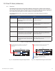
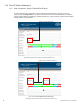
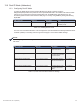
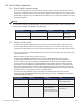


Table Of Contents
- Table 1-1, DSM3 Series Model Specifications
- Table 2-1, LEDs and Indications
- Table 3-1, Modem Community String Parameters — DOCSIS 2.0 (IPv4) Method
- Table 3-2, Modem Community String Parameters — DOCSIS 2.0+IPv6 Method
- Table 3-3, Trap Destination Addresses — DOCSIS 2.0 (IPv4) Method
- Table 3-4, Trap Destination Addresses — DOCSIS 2.0+IPv6 Method
- Table 3-5, Default atidoc.cfg Download Settings
- Table 3-6, Communications Parameters
- Table 4-1, DSM3 Series Communications Module Security Levels
- Table 4-3, Time Offset Values and Location Reference (offset +/- GMT)
- Table 5-1, Modem Firmware Upgrade SNMP Parameters
- Table 5-2, SNMP Parameters
- Table 5-3, DOCSIS Configurations File Values
- Table 6-1, SCTE-HMS MIB Files
- Table 6-2, Binary to Hex Conversions for Alarm Settings
- Table 6-3, Recommended Settings for DSM3 Series Analog Alarms
- Table 6-4, Recommended Settings for Discrete Alarms
- Table 6-5, DSM Alarm Setting Paramters
- Table 6-6, Status of Alarm Setting Download Parameters
- Table 6-7, SNMP Alarm Trap Varbinds and Explanations
- Table 6-8, Power Alarms: Classifications, Causes and Corrections
- Table 6-9, Battery Alarms: Classifications, Causes and Corrections
- Table 6-9, Alpha MIB Hierarchy
- Table 6-10, Alpha MIBs Examples
- Table 7-1, Tamper (TPR) Switch Specifications
- Table 7-2, ENV Connector and Pin Descriptions
- Table 7-3, I/O Port Specifications
- Table 7-4, I/O Port: Generic Device Specifications
- Table 7-5, LA-P-SM Monitoring Values
- Table 7-6, I/O Port: Heater Mat Control Specifications
- Table 7-7, Heater Mat OIDs and Functionality
- Table 7-8, Heater Mat MIB Reports
- Table 7-9, Generator Monitoring Values
- Table 9-1,SCTE-HMS Property Table
- Table 9-2, Rx/Tx Power LED Color Ranges
- Table 13-1, Single IP Mode versus Dual IP Mode
- Table 13-2, Enabling Dual IP mode
- Table 13-3, CPE Communications Module IP Settings
- Table 13-4, Available Download Options
- 1.0 Introduction
- 2.0 Overview
- 3.0 Network Configuration
- 3.1 Provisioning the DHCP Server with the MAC Addresses
- 3.2 Establishing IP Connectivity
- 3.3 The DOCSIS Configuration File
- 3.3.8 Changing Default atidoc03.cfg Download Settings
- 3.3.7 Proprietary Configuration File ‘atidoc03.cfg’
- 3.3.6 Sample DOCSIS Configuration File Entries — DOCSIS 2.0+IPv6
- 3.3.5 Sample DOCSIS Configuration File Entries — DOCSIS 2.0 (IPv4)
- 3.3.4 Setting SNMP Trap Destination Addresses — DOCSIS 2.0+IPv6 Method
- 3.3.3 Setting SNMP Trap Destination Addresses — DOCSIS 2.0 (IPv4) Method
- 3.3.2 Setting Modem Community Strings — DOCSIS 2.0+IPv6 Method
- 3.4 Setting Communication Options
- 4.0 Web Interface
- 4.1 Local Web Server Access
- 4.2 Remote Web Server Access
- 4.3 Navigating the Web Page
- 4.4 Verifying Communication Parameters
- 4.5 Verifying Power Supply and Battery Parameters
- 4.6 Remote Self Tests via the Web Page
- 4.7 Viewing HMS Alarm Status via the Web Page
- 4.8 Setting the I/O Controller via the Web Page
- 4.9 Viewing and Configuring Power Supply settings via the Web Page
- 4.10 Viewing and Configuring Generator Settings via the Web Page
- 4.11 Tools Menu – Constellation and Microreflections
- 4.12 Viewing AlphaApps Information via the Web Page
- 4.13 Battery Management
- 4.14 Viewing Power Supply Event and Configuration Logs
- 4.15 Battery Event Log
- 4.16 Viewing the Modem Event Log via the Web Page
- 5.0 Upgrading Firmware
- 6.0 Data Management
- 7.0 Installation
- 7.1 Verifying Power Supply Device Address
- 7.2 Installation / Replacement Procedure in XM3 Power Supplies
- 7.3 DSM3x LEDs and Connections
- 7.4 DSM3 LEDs and Connections
- 7.5 DPM LEDs and Connections
- 7.6 Connecting the RF Drop
- 7.7 Front Panel Connections
- 7.8 I/O Connections (TPR, ENV)
- 7.8.1 Tamper (TPR) Switch Interface
- 7.8.2 I/O Port Interface
- 7.8.3 Configuring I/O Port Connections
- 7.8.4 I/O Port: Generic Device
- 7.8.5 Connecting a Generic I/O Device
- 7.8.6 Configuring and Monitoring a Generic I/O Device
- 7.8.7 I/O Port: Lightning Arrestor (LA-P-SM)
- 7.8.8 Lightning Arrestor (LA-P-SM) Installation
- 7.8.9 Configuring the LA-P-SM
- 7.8.10 I/O Port: Heater Mat Control
- 7.8.11 Connecting the Battery Heater Mat Controller, continued
- 7.8.12 Configuring the Battery Heater Mat Controller
- 7.8.14 Configuring and Monitoring the DC Emergency Generator
- 8.0 Battery Sense Wire Kits
- 9.0 Start Up and Verification
- 10.0 Alpha MIB Parameters
- 11.0 Specifications
- 12.0 Glossary
- 13.0 Dual IP Mode (Addendum)
- 13.1 Overview
- 13.2 Web Comparison, Single IP Mode/Dual IP Mode
- 13.3 Configuring Dual IP Mode
- 13.3.3 Specifying atidoc03.cfg name and location via DHCP Tags
- 13.3.2 Changing Default atidoc03.cfg Download Settings in Dual IP Mode
- 13.3.1 atidoc03.cfg in Dual IP Mode
- 13.4 Dual IP SNMP Community Strings
- 13.5 Security in Dual IP Mode
- Fig. 1-1, AlphaNet DSM3x
- Fig. 1-2, AlphaNet DSM3
- Fig. 1-3, AlphaNet DPM
- Fig. 1-4, Side view, AlphaNet DSM3 Series
- Fig. 2-1, Representative System Arrangement
- Fig. 3-1, Locations of MAC Address Labels
- Fig. 3-2, Sample DOCSIS Configuration File — DOCSIS 2.0 (IPv4)
- Fig. 3-3, Sample DOCSIS Configuration File — DOCSIS 2.0+IPv6
- Fig. 4-1, DSM3 Series Web Page
- Fig. 4-2, Local Area Connection Properties Screen, Windows XP
- Fig. 4-3, Internet Protocol (TCP/IP) Properties Screen, Windows XP
- Fig. 4-4, Local Area Connection Properties Screen, Windows 7
- Fig. 4-5, Internet Protocol (TCP/IP) Properties Screen, Windows 7
- Fig. 4-6, Web Server Home Page
- Fig. 4-7, DSM3 Series Navigation Bar Items
- Fig. 4-8, Communication Parameters
- Fig. 4-9, Advanced Communication Parameters
- Fig. 4-10, Power Supply and Battery Parameters
- Fig. 4-11, Location of Start Test Button for Self Test
- Fig. 4-12, HMS Alarm Configuration
- Fig. 4-13, Advanced I/O Controller Status Screen
- Fig. 4-14, Advanced Power Supply Settings Screen
- Fig. 4-15, Advanced Generator Status Screen
- Fig. 4-16, QAM Constellation Tool
- Fig. 4-17, Normal - (Good Quality) and Individual Cell Characteristics
- Fig. 4-18, Fuzzy (Low CNR and/or Low MER) and Individual Cell Characteristics
- Fig. 4-19, Doughnuts (Coherent Interference) and Individual Cell Characteristics
- Fig. 4-20, Gaussian Noise and Individual Cell Characteristics
- Fig. 4-21, Rectangular vs. Square (I-Q Imbalance) and Entire Constellation Shape
- Fig. 4-22, Corners Squeezed to Center (Gain Compression) and Entire Constellation Shape
- Fig. 4-23, Circular Smear (Phase Noise) and Entire Constellation Shape
- Fig. 4-24, Twisted or Skewed (Quadrature Distortion) and Entire Constellation Shape
- Fig. 4-25, Microreflections Tool
- Fig. 4-26, Alpha Apps and Utility Status Parameters
- Fig. 4-27, Battery Management
- Fig. 4-28, Battery Model Selection
- Fig. 4-29, DSM3 System Log
- Fig. 4-30, Power Supply Event Log
- Fig. 4-31, Power Supply Configuration Log
- Fig. 4-33, Docsdev Event Log Screen
- Fig. 6-1, Sample Raw SNMP Alarm Trap
- Fig. 6-2, Sample Translated SNMP Alarm Trap
- Fig. 7-1, Captive Screw Locations
- Fig. 7-3, Connecting the Communications Module to the Inverter Module
- Fig. 7-2, The 18-pin Connector
- Fig. 7-4, DSM3x LEDs and Connectors
- Fig. 7-5, DSM3 LEDs and Connectors
- Fig. 7-6, DPM LEDs and Connectors
- Fig. 7-7, Connecting the RF Drop
- Fig. 7-8, System Interconnection Diagram
- Fig. 7-9, I/O (ENV) and Tamper Switch Interface (TPR) Connection Locations
- Fig. 8-1, 36V System, Single String
- Fig. 8-2, 36V System, Dual String
- Fig. 9-1, XM3 Smart Display Screens
- Fig. 9-2, Communications Section - General Page
- Fig. 9-3, Power Supply Section - General Page
- Fig. 9-4, LED Functionality and Indications
- Fig. 9-5, DSM3 Series Web Page, RF Power Level Indicators
- Fig. 13-1, Simplified Block Diagram Single IP Mode
- Fig 13-2, Simplified Block Diagram Dual IP Mode
- Fig. 13-3, Single IP DSM3 Series Web Page
- Fig. 13-4, Dual IP DSM3 Series Web Page
- Fig. 13-5, Dual IP Configuration Settings for DSM3 Web Server Communications Page
- Fig. 13-6, Dual IP Parameters for DSM3 Web Server General Page

103745-814-B11-001, Rev. C (03/2014)
13.0 Dual IP Mode (Addendum)
13.4 Dual IP SNMP Community Strings
The Communications Module community strings used for the CPE Communications Module in Dual IP
mode can be congured by the operator. The default Communications Module read-only community string
is AlphaGet. The default read-write community string is AlphaSet. These settings can be congured with
the DOCSIS Conguration File, the DSM3 Setup File (aitdoc03.cfg) or remotely using SNMP by including
the parameters below:
MIB Parameter Object ID Description Value
atiMgmtSnmpCommGet 1.3.6.1.4.1.926.1.3.1.4.1.0 Read Community String AlphaGet (default)
[desired value]
atiMgmtSnmpCommSet 1.3.6.1.4.1.926.1.3.1.4.2.0 Read/Write Community String AlphaSet (default)
[desired value]
13.5 Security in Dual IP Mode
In Dual IP mode, additional SNMP security to the DSM3 Series proprietary MIBs is required since the
Communications Module and power supply data is exposed on the CPE network, which may be more
vulnerable to packet snifng and community string deciphering than on the secure cable modem network.
There are two methods of providing SNMP Security in Dual IP mode: the Data Access Key (default), and
the Secure Access List.
Method 1: Dual IP Security Using the Data Access Key
In Dual IP mode atiMgmtSnmpAlphaSetAccess is the only SNMP parameter within the Alpha
proprietary MIB with SNMP write access on the CPE network by default. When this parameter is
set to the value of the parameter atiMgmtSnmpAlphaSetKey, the data access key, SNMP read/write
access is granted to all parameters in the Alpha MIB tree with read/write attributes. When this access
is granted, the value of atiMgmtSnmpCPESetEnabled is automatically changed to "2" (enabled). After
the operator is nished setting the SNMP variables, SNMP write access can be disabled by setting the
atiMgmtSnmpCPESetEnabled to "1" or by setting atiMgmtSnmpAlphaSetAccess to any value other than
the data access key or by performing a reset to the DSM3 Series.
The data access key parameters can be changed from the default values through the DOCSIS
Conguration File, the DSM3 Series Setup File (atidoc03.cfg) or remotely using SNMP by including the
following Alpha MIB parameters:
MIB Parameter Object ID Description Value
atiMgmtSnmpAlphaSetAccess 1.3.6.1.4.1.926.1.3.1.3.3.0 Set to Access Key Set to match the value of
atiMgmtSnmpAlphaSetKey
atiMgmtSnmpAlphaSetKey 1.3.6.1.4.1.926.1.3.1.3.4.0 Data Access Key (Dual IP) CIBSET (default)
atiMgmtSnmpCPESetEnabled 1.3.6.1.4.1.926.1.3.1.3.5.0 Corresponds to whether
or not the action taken on
atiMgmtSnmpAlphaSetKey was
successful. Once enabled, writing
1 to this variable will disable CPE
sets.
1 = Disabled (False)
2 = Enabled (True)
Table 13-6, Data Access Key Parameters
Table 13-5, Community Strings
These community strings are only applicable for CPE access in Dual IP mode. CM access in both Single
IP and Dual IP modes use standard DOCSIS community strings set through the modem conguration le's
docsDevNmAccessTable. See Sections 3.3.1 and 3.3.2.
NOTE: