
Manual
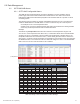
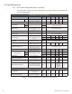
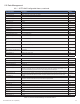
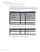
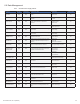
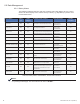
Table Of Contents
- Table 1-1, DSM3 Series Model Specifications
- Table 2-1, LEDs and Indications
- Table 3-1, Modem Community String Parameters — DOCSIS 2.0 (IPv4) Method
- Table 3-2, Modem Community String Parameters — DOCSIS 2.0+IPv6 Method
- Table 3-3, Trap Destination Addresses — DOCSIS 2.0 (IPv4) Method
- Table 3-4, Trap Destination Addresses — DOCSIS 2.0+IPv6 Method
- Table 3-5, Default atidoc.cfg Download Settings
- Table 3-6, Communications Parameters
- Table 4-1, DSM3 Series Communications Module Security Levels
- Table 4-3, Time Offset Values and Location Reference (offset +/- GMT)
- Table 5-1, Modem Firmware Upgrade SNMP Parameters
- Table 5-2, SNMP Parameters
- Table 5-3, DOCSIS Configurations File Values
- Table 6-1, SCTE-HMS MIB Files
- Table 6-2, Binary to Hex Conversions for Alarm Settings
- Table 6-3, Recommended Settings for DSM3 Series Analog Alarms
- Table 6-4, Recommended Settings for Discrete Alarms
- Table 6-5, DSM Alarm Setting Paramters
- Table 6-6, Status of Alarm Setting Download Parameters
- Table 6-7, SNMP Alarm Trap Varbinds and Explanations
- Table 6-8, Power Alarms: Classifications, Causes and Corrections
- Table 6-9, Battery Alarms: Classifications, Causes and Corrections
- Table 6-9, Alpha MIB Hierarchy
- Table 6-10, Alpha MIBs Examples
- Table 7-1, Tamper (TPR) Switch Specifications
- Table 7-2, ENV Connector and Pin Descriptions
- Table 7-3, I/O Port Specifications
- Table 7-4, I/O Port: Generic Device Specifications
- Table 7-5, LA-P-SM Monitoring Values
- Table 7-6, I/O Port: Heater Mat Control Specifications
- Table 7-7, Heater Mat OIDs and Functionality
- Table 7-8, Heater Mat MIB Reports
- Table 7-9, Generator Monitoring Values
- Table 9-1,SCTE-HMS Property Table
- Table 9-2, Rx/Tx Power LED Color Ranges
- Table 13-1, Single IP Mode versus Dual IP Mode
- Table 13-2, Enabling Dual IP mode
- Table 13-3, CPE Communications Module IP Settings
- Table 13-4, Available Download Options
- 1.0 Introduction
- 2.0 Overview
- 3.0 Network Configuration
- 3.1 Provisioning the DHCP Server with the MAC Addresses
- 3.2 Establishing IP Connectivity
- 3.3 The DOCSIS Configuration File
- 3.3.8 Changing Default atidoc03.cfg Download Settings
- 3.3.7 Proprietary Configuration File ‘atidoc03.cfg’
- 3.3.6 Sample DOCSIS Configuration File Entries — DOCSIS 2.0+IPv6
- 3.3.5 Sample DOCSIS Configuration File Entries — DOCSIS 2.0 (IPv4)
- 3.3.4 Setting SNMP Trap Destination Addresses — DOCSIS 2.0+IPv6 Method
- 3.3.3 Setting SNMP Trap Destination Addresses — DOCSIS 2.0 (IPv4) Method
- 3.3.2 Setting Modem Community Strings — DOCSIS 2.0+IPv6 Method
- 3.4 Setting Communication Options
- 4.0 Web Interface
- 4.1 Local Web Server Access
- 4.2 Remote Web Server Access
- 4.3 Navigating the Web Page
- 4.4 Verifying Communication Parameters
- 4.5 Verifying Power Supply and Battery Parameters
- 4.6 Remote Self Tests via the Web Page
- 4.7 Viewing HMS Alarm Status via the Web Page
- 4.8 Setting the I/O Controller via the Web Page
- 4.9 Viewing and Configuring Power Supply settings via the Web Page
- 4.10 Viewing and Configuring Generator Settings via the Web Page
- 4.11 Tools Menu – Constellation and Microreflections
- 4.12 Viewing AlphaApps Information via the Web Page
- 4.13 Battery Management
- 4.14 Viewing Power Supply Event and Configuration Logs
- 4.15 Battery Event Log
- 4.16 Viewing the Modem Event Log via the Web Page
- 5.0 Upgrading Firmware
- 6.0 Data Management
- 7.0 Installation
- 7.1 Verifying Power Supply Device Address
- 7.2 Installation / Replacement Procedure in XM3 Power Supplies
- 7.3 DSM3x LEDs and Connections
- 7.4 DSM3 LEDs and Connections
- 7.5 DPM LEDs and Connections
- 7.6 Connecting the RF Drop
- 7.7 Front Panel Connections
- 7.8 I/O Connections (TPR, ENV)
- 7.8.1 Tamper (TPR) Switch Interface
- 7.8.2 I/O Port Interface
- 7.8.3 Configuring I/O Port Connections
- 7.8.4 I/O Port: Generic Device
- 7.8.5 Connecting a Generic I/O Device
- 7.8.6 Configuring and Monitoring a Generic I/O Device
- 7.8.7 I/O Port: Lightning Arrestor (LA-P-SM)
- 7.8.8 Lightning Arrestor (LA-P-SM) Installation
- 7.8.9 Configuring the LA-P-SM
- 7.8.10 I/O Port: Heater Mat Control
- 7.8.11 Connecting the Battery Heater Mat Controller, continued
- 7.8.12 Configuring the Battery Heater Mat Controller
- 7.8.14 Configuring and Monitoring the DC Emergency Generator
- 8.0 Battery Sense Wire Kits
- 9.0 Start Up and Verification
- 10.0 Alpha MIB Parameters
- 11.0 Specifications
- 12.0 Glossary
- 13.0 Dual IP Mode (Addendum)
- 13.1 Overview
- 13.2 Web Comparison, Single IP Mode/Dual IP Mode
- 13.3 Configuring Dual IP Mode
- 13.3.3 Specifying atidoc03.cfg name and location via DHCP Tags
- 13.3.2 Changing Default atidoc03.cfg Download Settings in Dual IP Mode
- 13.3.1 atidoc03.cfg in Dual IP Mode
- 13.4 Dual IP SNMP Community Strings
- 13.5 Security in Dual IP Mode
- Fig. 1-1, AlphaNet DSM3x
- Fig. 1-2, AlphaNet DSM3
- Fig. 1-3, AlphaNet DPM
- Fig. 1-4, Side view, AlphaNet DSM3 Series
- Fig. 2-1, Representative System Arrangement
- Fig. 3-1, Locations of MAC Address Labels
- Fig. 3-2, Sample DOCSIS Configuration File — DOCSIS 2.0 (IPv4)
- Fig. 3-3, Sample DOCSIS Configuration File — DOCSIS 2.0+IPv6
- Fig. 4-1, DSM3 Series Web Page
- Fig. 4-2, Local Area Connection Properties Screen, Windows XP
- Fig. 4-3, Internet Protocol (TCP/IP) Properties Screen, Windows XP
- Fig. 4-4, Local Area Connection Properties Screen, Windows 7
- Fig. 4-5, Internet Protocol (TCP/IP) Properties Screen, Windows 7
- Fig. 4-6, Web Server Home Page
- Fig. 4-7, DSM3 Series Navigation Bar Items
- Fig. 4-8, Communication Parameters
- Fig. 4-9, Advanced Communication Parameters
- Fig. 4-10, Power Supply and Battery Parameters
- Fig. 4-11, Location of Start Test Button for Self Test
- Fig. 4-12, HMS Alarm Configuration
- Fig. 4-13, Advanced I/O Controller Status Screen
- Fig. 4-14, Advanced Power Supply Settings Screen
- Fig. 4-15, Advanced Generator Status Screen
- Fig. 4-16, QAM Constellation Tool
- Fig. 4-17, Normal - (Good Quality) and Individual Cell Characteristics
- Fig. 4-18, Fuzzy (Low CNR and/or Low MER) and Individual Cell Characteristics
- Fig. 4-19, Doughnuts (Coherent Interference) and Individual Cell Characteristics
- Fig. 4-20, Gaussian Noise and Individual Cell Characteristics
- Fig. 4-21, Rectangular vs. Square (I-Q Imbalance) and Entire Constellation Shape
- Fig. 4-22, Corners Squeezed to Center (Gain Compression) and Entire Constellation Shape
- Fig. 4-23, Circular Smear (Phase Noise) and Entire Constellation Shape
- Fig. 4-24, Twisted or Skewed (Quadrature Distortion) and Entire Constellation Shape
- Fig. 4-25, Microreflections Tool
- Fig. 4-26, Alpha Apps and Utility Status Parameters
- Fig. 4-27, Battery Management
- Fig. 4-28, Battery Model Selection
- Fig. 4-29, DSM3 System Log
- Fig. 4-30, Power Supply Event Log
- Fig. 4-31, Power Supply Configuration Log
- Fig. 4-33, Docsdev Event Log Screen
- Fig. 6-1, Sample Raw SNMP Alarm Trap
- Fig. 6-2, Sample Translated SNMP Alarm Trap
- Fig. 7-1, Captive Screw Locations
- Fig. 7-3, Connecting the Communications Module to the Inverter Module
- Fig. 7-2, The 18-pin Connector
- Fig. 7-4, DSM3x LEDs and Connectors
- Fig. 7-5, DSM3 LEDs and Connectors
- Fig. 7-6, DPM LEDs and Connectors
- Fig. 7-7, Connecting the RF Drop
- Fig. 7-8, System Interconnection Diagram
- Fig. 7-9, I/O (ENV) and Tamper Switch Interface (TPR) Connection Locations
- Fig. 8-1, 36V System, Single String
- Fig. 8-2, 36V System, Dual String
- Fig. 9-1, XM3 Smart Display Screens
- Fig. 9-2, Communications Section - General Page
- Fig. 9-3, Power Supply Section - General Page
- Fig. 9-4, LED Functionality and Indications
- Fig. 9-5, DSM3 Series Web Page, RF Power Level Indicators
- Fig. 13-1, Simplified Block Diagram Single IP Mode
- Fig 13-2, Simplified Block Diagram Dual IP Mode
- Fig. 13-3, Single IP DSM3 Series Web Page
- Fig. 13-4, Dual IP DSM3 Series Web Page
- Fig. 13-5, Dual IP Configuration Settings for DSM3 Web Server Communications Page
- Fig. 13-6, Dual IP Parameters for DSM3 Web Server General Page

52
745-814-B11-001, Rev. C (03/2014)
6.2.1 SCTE-HMS Congurable Alarms, continued
Table 6-3, Recommended Settings for DSM3 Series Analog Alarms
Analog Alarms and Common Settings
Analog Alarms Description
Alarm
Enable
LOLO LO HI HIHI Deadband
psTotalStringVoltage 36V
Scaled representation of the full
battery string in 1/100 Volts units
0x0F 3300 3500 4520 4570 50
Individual Battery Voltage
Battery Voltage of 12V Battery in
1/100 Volts units
0x0F 1050 1150 1530 1550 20
psInputVoltage
120V
Scaled representation of the input
line voltage in 1/100 Volts units
0x0F
Varies by site. The XM3 will switch to standby at
nominal +15% -30%
220V 0x0F
psRMSCurrentIn
Scaled representation of the Power
Supply's RMS curent in 1/100 A
units
0x00 Set as desired per site
psPowerIn
Representation of the Power
Supply's input power in 1 W units
0x00 Set as desired per site
psFrequencyOut
Representation of Power Supply's
output frequency in 1/100 Hz units
0x00 Set as desired per site
psOutputVoltage
Scaled representation of the Power
Supply output voltage in 1/100
Volts units
0x0F 4300 4550 5050 5300 200
0x0F 5650 6000 6600 7000 200
0x0F 7800 8200 9150 9300 200
psPowerOut
Representation of Power Supply
output power in 1W units
0x00
It is recommended that psOutputCurrent be used
for output alarms.
psStringChargeCurrent
Battery string charge current,
scaled in 1/100 Amp units
0x0C Disable Disable 1200 1250 20
psStringDischargeCurrent
Scaled representation of battery
string discharge current. This is an
RMS value in 1/100 Amps
0x00
Set as desired per site
psStringFloat
Battery string oat charge current,
scaled in 1/100 Amp units
0x0C Disable Disable 1200 1250 20
psOutputCurrent
15A
Scaled representation of Power
Supply RMS currnt in 1/100 Amp
units
0x0C Disable Disable 1650 1720 20
18A 0x0C Disable Disable 1980 2060 20
22A 0x0C Disable Disable 2420 2530 40
psTemperature
-40 to +80 degrees C
0x0F Varies by site
docsIfDownChannelPower
The CM's receive RF power scaled
in 1/10 dBmV units
0x0F -150 -10 10 150 15
docsIfCmStatusTxPower
The CM's transmit RF power
scaled in 1/10 dBmV units
0x0C 0 0 500 550 15
atiBBsysViewTimeInStandby
Time in seconds that the Power
Supply's inverter is currently
running due to outage or self test
0x0C 0 0
Set as
desired for
notication
of extended
outage
10
Alarms for Optional Generator
GenVBatIgnition
Scaled representation of the
generator's ignition battery in
1/100 Volts
0x0F 1150 1200 1500 1550 20
genEnclosureTemperature
Temperature inside generator's
enclosure in degrees C
0x09 -40 0 0 55 5
The following table displays the various analog alarms with common settings for the DSM3 Series
Communications Module.
6.0 Data Management