
Manual
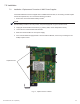
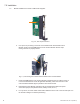
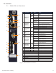
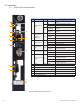
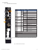
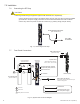
Table Of Contents
- Table 1-1, DSM3 Series Model Specifications
- Table 2-1, LEDs and Indications
- Table 3-1, Modem Community String Parameters — DOCSIS 2.0 (IPv4) Method
- Table 3-2, Modem Community String Parameters — DOCSIS 2.0+IPv6 Method
- Table 3-3, Trap Destination Addresses — DOCSIS 2.0 (IPv4) Method
- Table 3-4, Trap Destination Addresses — DOCSIS 2.0+IPv6 Method
- Table 3-5, Default atidoc.cfg Download Settings
- Table 3-6, Communications Parameters
- Table 4-1, DSM3 Series Communications Module Security Levels
- Table 4-3, Time Offset Values and Location Reference (offset +/- GMT)
- Table 5-1, Modem Firmware Upgrade SNMP Parameters
- Table 5-2, SNMP Parameters
- Table 5-3, DOCSIS Configurations File Values
- Table 6-1, SCTE-HMS MIB Files
- Table 6-2, Binary to Hex Conversions for Alarm Settings
- Table 6-3, Recommended Settings for DSM3 Series Analog Alarms
- Table 6-4, Recommended Settings for Discrete Alarms
- Table 6-5, DSM Alarm Setting Paramters
- Table 6-6, Status of Alarm Setting Download Parameters
- Table 6-7, SNMP Alarm Trap Varbinds and Explanations
- Table 6-8, Power Alarms: Classifications, Causes and Corrections
- Table 6-9, Battery Alarms: Classifications, Causes and Corrections
- Table 6-9, Alpha MIB Hierarchy
- Table 6-10, Alpha MIBs Examples
- Table 7-1, Tamper (TPR) Switch Specifications
- Table 7-2, ENV Connector and Pin Descriptions
- Table 7-3, I/O Port Specifications
- Table 7-4, I/O Port: Generic Device Specifications
- Table 7-5, LA-P-SM Monitoring Values
- Table 7-6, I/O Port: Heater Mat Control Specifications
- Table 7-7, Heater Mat OIDs and Functionality
- Table 7-8, Heater Mat MIB Reports
- Table 7-9, Generator Monitoring Values
- Table 9-1,SCTE-HMS Property Table
- Table 9-2, Rx/Tx Power LED Color Ranges
- Table 13-1, Single IP Mode versus Dual IP Mode
- Table 13-2, Enabling Dual IP mode
- Table 13-3, CPE Communications Module IP Settings
- Table 13-4, Available Download Options
- 1.0 Introduction
- 2.0 Overview
- 3.0 Network Configuration
- 3.1 Provisioning the DHCP Server with the MAC Addresses
- 3.2 Establishing IP Connectivity
- 3.3 The DOCSIS Configuration File
- 3.3.8 Changing Default atidoc03.cfg Download Settings
- 3.3.7 Proprietary Configuration File ‘atidoc03.cfg’
- 3.3.6 Sample DOCSIS Configuration File Entries — DOCSIS 2.0+IPv6
- 3.3.5 Sample DOCSIS Configuration File Entries — DOCSIS 2.0 (IPv4)
- 3.3.4 Setting SNMP Trap Destination Addresses — DOCSIS 2.0+IPv6 Method
- 3.3.3 Setting SNMP Trap Destination Addresses — DOCSIS 2.0 (IPv4) Method
- 3.3.2 Setting Modem Community Strings — DOCSIS 2.0+IPv6 Method
- 3.4 Setting Communication Options
- 4.0 Web Interface
- 4.1 Local Web Server Access
- 4.2 Remote Web Server Access
- 4.3 Navigating the Web Page
- 4.4 Verifying Communication Parameters
- 4.5 Verifying Power Supply and Battery Parameters
- 4.6 Remote Self Tests via the Web Page
- 4.7 Viewing HMS Alarm Status via the Web Page
- 4.8 Setting the I/O Controller via the Web Page
- 4.9 Viewing and Configuring Power Supply settings via the Web Page
- 4.10 Viewing and Configuring Generator Settings via the Web Page
- 4.11 Tools Menu – Constellation and Microreflections
- 4.12 Viewing AlphaApps Information via the Web Page
- 4.13 Battery Management
- 4.14 Viewing Power Supply Event and Configuration Logs
- 4.15 Battery Event Log
- 4.16 Viewing the Modem Event Log via the Web Page
- 5.0 Upgrading Firmware
- 6.0 Data Management
- 7.0 Installation
- 7.1 Verifying Power Supply Device Address
- 7.2 Installation / Replacement Procedure in XM3 Power Supplies
- 7.3 DSM3x LEDs and Connections
- 7.4 DSM3 LEDs and Connections
- 7.5 DPM LEDs and Connections
- 7.6 Connecting the RF Drop
- 7.7 Front Panel Connections
- 7.8 I/O Connections (TPR, ENV)
- 7.8.1 Tamper (TPR) Switch Interface
- 7.8.2 I/O Port Interface
- 7.8.3 Configuring I/O Port Connections
- 7.8.4 I/O Port: Generic Device
- 7.8.5 Connecting a Generic I/O Device
- 7.8.6 Configuring and Monitoring a Generic I/O Device
- 7.8.7 I/O Port: Lightning Arrestor (LA-P-SM)
- 7.8.8 Lightning Arrestor (LA-P-SM) Installation
- 7.8.9 Configuring the LA-P-SM
- 7.8.10 I/O Port: Heater Mat Control
- 7.8.11 Connecting the Battery Heater Mat Controller, continued
- 7.8.12 Configuring the Battery Heater Mat Controller
- 7.8.14 Configuring and Monitoring the DC Emergency Generator
- 8.0 Battery Sense Wire Kits
- 9.0 Start Up and Verification
- 10.0 Alpha MIB Parameters
- 11.0 Specifications
- 12.0 Glossary
- 13.0 Dual IP Mode (Addendum)
- 13.1 Overview
- 13.2 Web Comparison, Single IP Mode/Dual IP Mode
- 13.3 Configuring Dual IP Mode
- 13.3.3 Specifying atidoc03.cfg name and location via DHCP Tags
- 13.3.2 Changing Default atidoc03.cfg Download Settings in Dual IP Mode
- 13.3.1 atidoc03.cfg in Dual IP Mode
- 13.4 Dual IP SNMP Community Strings
- 13.5 Security in Dual IP Mode
- Fig. 1-1, AlphaNet DSM3x
- Fig. 1-2, AlphaNet DSM3
- Fig. 1-3, AlphaNet DPM
- Fig. 1-4, Side view, AlphaNet DSM3 Series
- Fig. 2-1, Representative System Arrangement
- Fig. 3-1, Locations of MAC Address Labels
- Fig. 3-2, Sample DOCSIS Configuration File — DOCSIS 2.0 (IPv4)
- Fig. 3-3, Sample DOCSIS Configuration File — DOCSIS 2.0+IPv6
- Fig. 4-1, DSM3 Series Web Page
- Fig. 4-2, Local Area Connection Properties Screen, Windows XP
- Fig. 4-3, Internet Protocol (TCP/IP) Properties Screen, Windows XP
- Fig. 4-4, Local Area Connection Properties Screen, Windows 7
- Fig. 4-5, Internet Protocol (TCP/IP) Properties Screen, Windows 7
- Fig. 4-6, Web Server Home Page
- Fig. 4-7, DSM3 Series Navigation Bar Items
- Fig. 4-8, Communication Parameters
- Fig. 4-9, Advanced Communication Parameters
- Fig. 4-10, Power Supply and Battery Parameters
- Fig. 4-11, Location of Start Test Button for Self Test
- Fig. 4-12, HMS Alarm Configuration
- Fig. 4-13, Advanced I/O Controller Status Screen
- Fig. 4-14, Advanced Power Supply Settings Screen
- Fig. 4-15, Advanced Generator Status Screen
- Fig. 4-16, QAM Constellation Tool
- Fig. 4-17, Normal - (Good Quality) and Individual Cell Characteristics
- Fig. 4-18, Fuzzy (Low CNR and/or Low MER) and Individual Cell Characteristics
- Fig. 4-19, Doughnuts (Coherent Interference) and Individual Cell Characteristics
- Fig. 4-20, Gaussian Noise and Individual Cell Characteristics
- Fig. 4-21, Rectangular vs. Square (I-Q Imbalance) and Entire Constellation Shape
- Fig. 4-22, Corners Squeezed to Center (Gain Compression) and Entire Constellation Shape
- Fig. 4-23, Circular Smear (Phase Noise) and Entire Constellation Shape
- Fig. 4-24, Twisted or Skewed (Quadrature Distortion) and Entire Constellation Shape
- Fig. 4-25, Microreflections Tool
- Fig. 4-26, Alpha Apps and Utility Status Parameters
- Fig. 4-27, Battery Management
- Fig. 4-28, Battery Model Selection
- Fig. 4-29, DSM3 System Log
- Fig. 4-30, Power Supply Event Log
- Fig. 4-31, Power Supply Configuration Log
- Fig. 4-33, Docsdev Event Log Screen
- Fig. 6-1, Sample Raw SNMP Alarm Trap
- Fig. 6-2, Sample Translated SNMP Alarm Trap
- Fig. 7-1, Captive Screw Locations
- Fig. 7-3, Connecting the Communications Module to the Inverter Module
- Fig. 7-2, The 18-pin Connector
- Fig. 7-4, DSM3x LEDs and Connectors
- Fig. 7-5, DSM3 LEDs and Connectors
- Fig. 7-6, DPM LEDs and Connectors
- Fig. 7-7, Connecting the RF Drop
- Fig. 7-8, System Interconnection Diagram
- Fig. 7-9, I/O (ENV) and Tamper Switch Interface (TPR) Connection Locations
- Fig. 8-1, 36V System, Single String
- Fig. 8-2, 36V System, Dual String
- Fig. 9-1, XM3 Smart Display Screens
- Fig. 9-2, Communications Section - General Page
- Fig. 9-3, Power Supply Section - General Page
- Fig. 9-4, LED Functionality and Indications
- Fig. 9-5, DSM3 Series Web Page, RF Power Level Indicators
- Fig. 13-1, Simplified Block Diagram Single IP Mode
- Fig 13-2, Simplified Block Diagram Dual IP Mode
- Fig. 13-3, Single IP DSM3 Series Web Page
- Fig. 13-4, Dual IP DSM3 Series Web Page
- Fig. 13-5, Dual IP Configuration Settings for DSM3 Web Server Communications Page
- Fig. 13-6, Dual IP Parameters for DSM3 Web Server General Page

63745-814-B11-001, Rev. C (03/2014)
6.3 The Alpha MIBs
6.3.1 The Alpha MIB Structure
Measurements and settings for the power supply, generator, batteries and DSM are accessed
using Simple Network Management Protocol (SNMP) through the Alpha Management Information
Base (MIB) les.
The Alpha MIB is dened within the enterprise branch of the MIB tree starting at 1.3.6.1.4.1.926
and is organized into the following branches:
6.0 Data Management
Refer to Section 10.0, Alpha MIB Parameters for further details regarding the Alpha MIBs.
Alpha CIB Tables – atiTables (1.3.6.1.4.1.926.1.2.1)
Power supply, generator, battery and DSM3 data and settings are located in the CIB Tables branch (atiCibTables). The tables are sorted
into the following categories:
1. Discretes – XM3 major alarms & installed XM3 options.
2. Analogs – Voltages, currents, frequencies, temperatures.
3. Counters – Batteries per string, number of strings, XM3 Self Test schedule, device address, total run time and conguration settings.
4. Version – Device version information.
Alpha Management – atiManagement (1.3.6.1.4.1.926.1.3)
Advanced DSM3 settings are located in the Alpha management branch (atiManagement) and the settings are split between SNMP and
system-related settings.
1. SNMP Management – atiMgntSnmp (1.3.6.1.4.1.926.1.3.1)
SNMP Trap tables, SNMP access, Community Strings and SNMP Trap controls.
1.1 SNMP Trap Table – Table of SNMP trap addresses.
1.2 SNMP Access Table – Table of SNMP access addresses.
1.3 SNMP Access – Device accessibility via SNMPv1 & SNMPv2.
1.4 CPE Mode – Enable/disable Dual IP and Static IP settings.
1.5 Community Strings – Get, set and trap community strings.
1.6 SNMP Trap controls – Trap on normal, send count, SNMP timeout.
2. System Management – atiMgmtSys (1.3.6.1.4.1.926.1.3.2)
Download, Web server, SNTP server IP addresses, enclosure environmental controller, general controls (tamper polarity).
2.1 Download – DSM3 Proprietary Conguration File settings.
2.2 System Access – Enable/disable Web Page & Text Page - applies to DSM1 & DSM2 only.
2.3 HTTP Access – Enable/disable Web page – DSM3.
2.4 System Servers – Simple Network Time Protocol server (SNTP) IP address.
2.5 Temperature Manager – Battery heater mat or cooler settings.
2.6 Phone Home – IP address and timer settings.
2.7 General Controls – Tamper switch polarity and internal bus data size.
2.8 General Info – Base conguration of the device. i.e. DSM3, DSM3 Series, DPM.
2.9 Non-volatile Memory Defaults – Factory and custom defaults.
Alpha Product Platforms – atiProductPlatforms (1.3.6.1.4.1.926.1.4)
System power supply parameters are located the Alpha Product Platforms branch (atiProductPlatforms).
1. Broadband UPS
System View – Self Test, alarms, scalars, and counters reported by the host device.
1.1 Selects – Start/stop and prevention and System Control Manager.
1.2 Alarms – Status of major and minor alarm, Self Test, temperature probe and input power.
1.3 Scalars – Power supply input voltage, frequency and current. Battery voltage and temperature. Charger settings.
1.4 Counters – Self Test and inverter counters.
2. System Logs – atiProductPlatforms (1.3.6.1.4.1.926.1.4.1.2)
2.1 Events Table
2.2 Cong Table
2.3 Perform Table
3. System Apps – atiProductPlatforms (1.3.6.1.4.1.926.1.4.1.3)
3.1 Power Supply Health
3.2 Battery Status
3.3 Utility Quality
Table 6-11, Alpha MIBs Examples