
Manual
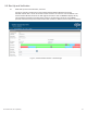
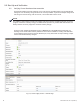
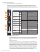
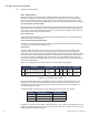
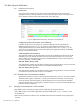
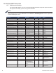
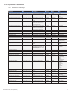
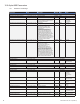
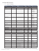
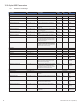
Table Of Contents
- Table 1-1, DSM3 Series Model Specifications
- Table 2-1, LEDs and Indications
- Table 3-1, Modem Community String Parameters — DOCSIS 2.0 (IPv4) Method
- Table 3-2, Modem Community String Parameters — DOCSIS 2.0+IPv6 Method
- Table 3-3, Trap Destination Addresses — DOCSIS 2.0 (IPv4) Method
- Table 3-4, Trap Destination Addresses — DOCSIS 2.0+IPv6 Method
- Table 3-5, Default atidoc.cfg Download Settings
- Table 3-6, Communications Parameters
- Table 4-1, DSM3 Series Communications Module Security Levels
- Table 4-3, Time Offset Values and Location Reference (offset +/- GMT)
- Table 5-1, Modem Firmware Upgrade SNMP Parameters
- Table 5-2, SNMP Parameters
- Table 5-3, DOCSIS Configurations File Values
- Table 6-1, SCTE-HMS MIB Files
- Table 6-2, Binary to Hex Conversions for Alarm Settings
- Table 6-3, Recommended Settings for DSM3 Series Analog Alarms
- Table 6-4, Recommended Settings for Discrete Alarms
- Table 6-5, DSM Alarm Setting Paramters
- Table 6-6, Status of Alarm Setting Download Parameters
- Table 6-7, SNMP Alarm Trap Varbinds and Explanations
- Table 6-8, Power Alarms: Classifications, Causes and Corrections
- Table 6-9, Battery Alarms: Classifications, Causes and Corrections
- Table 6-9, Alpha MIB Hierarchy
- Table 6-10, Alpha MIBs Examples
- Table 7-1, Tamper (TPR) Switch Specifications
- Table 7-2, ENV Connector and Pin Descriptions
- Table 7-3, I/O Port Specifications
- Table 7-4, I/O Port: Generic Device Specifications
- Table 7-5, LA-P-SM Monitoring Values
- Table 7-6, I/O Port: Heater Mat Control Specifications
- Table 7-7, Heater Mat OIDs and Functionality
- Table 7-8, Heater Mat MIB Reports
- Table 7-9, Generator Monitoring Values
- Table 9-1,SCTE-HMS Property Table
- Table 9-2, Rx/Tx Power LED Color Ranges
- Table 13-1, Single IP Mode versus Dual IP Mode
- Table 13-2, Enabling Dual IP mode
- Table 13-3, CPE Communications Module IP Settings
- Table 13-4, Available Download Options
- 1.0 Introduction
- 2.0 Overview
- 3.0 Network Configuration
- 3.1 Provisioning the DHCP Server with the MAC Addresses
- 3.2 Establishing IP Connectivity
- 3.3 The DOCSIS Configuration File
- 3.3.8 Changing Default atidoc03.cfg Download Settings
- 3.3.7 Proprietary Configuration File ‘atidoc03.cfg’
- 3.3.6 Sample DOCSIS Configuration File Entries — DOCSIS 2.0+IPv6
- 3.3.5 Sample DOCSIS Configuration File Entries — DOCSIS 2.0 (IPv4)
- 3.3.4 Setting SNMP Trap Destination Addresses — DOCSIS 2.0+IPv6 Method
- 3.3.3 Setting SNMP Trap Destination Addresses — DOCSIS 2.0 (IPv4) Method
- 3.3.2 Setting Modem Community Strings — DOCSIS 2.0+IPv6 Method
- 3.4 Setting Communication Options
- 4.0 Web Interface
- 4.1 Local Web Server Access
- 4.2 Remote Web Server Access
- 4.3 Navigating the Web Page
- 4.4 Verifying Communication Parameters
- 4.5 Verifying Power Supply and Battery Parameters
- 4.6 Remote Self Tests via the Web Page
- 4.7 Viewing HMS Alarm Status via the Web Page
- 4.8 Setting the I/O Controller via the Web Page
- 4.9 Viewing and Configuring Power Supply settings via the Web Page
- 4.10 Viewing and Configuring Generator Settings via the Web Page
- 4.11 Tools Menu – Constellation and Microreflections
- 4.12 Viewing AlphaApps Information via the Web Page
- 4.13 Battery Management
- 4.14 Viewing Power Supply Event and Configuration Logs
- 4.15 Battery Event Log
- 4.16 Viewing the Modem Event Log via the Web Page
- 5.0 Upgrading Firmware
- 6.0 Data Management
- 7.0 Installation
- 7.1 Verifying Power Supply Device Address
- 7.2 Installation / Replacement Procedure in XM3 Power Supplies
- 7.3 DSM3x LEDs and Connections
- 7.4 DSM3 LEDs and Connections
- 7.5 DPM LEDs and Connections
- 7.6 Connecting the RF Drop
- 7.7 Front Panel Connections
- 7.8 I/O Connections (TPR, ENV)
- 7.8.1 Tamper (TPR) Switch Interface
- 7.8.2 I/O Port Interface
- 7.8.3 Configuring I/O Port Connections
- 7.8.4 I/O Port: Generic Device
- 7.8.5 Connecting a Generic I/O Device
- 7.8.6 Configuring and Monitoring a Generic I/O Device
- 7.8.7 I/O Port: Lightning Arrestor (LA-P-SM)
- 7.8.8 Lightning Arrestor (LA-P-SM) Installation
- 7.8.9 Configuring the LA-P-SM
- 7.8.10 I/O Port: Heater Mat Control
- 7.8.11 Connecting the Battery Heater Mat Controller, continued
- 7.8.12 Configuring the Battery Heater Mat Controller
- 7.8.14 Configuring and Monitoring the DC Emergency Generator
- 8.0 Battery Sense Wire Kits
- 9.0 Start Up and Verification
- 10.0 Alpha MIB Parameters
- 11.0 Specifications
- 12.0 Glossary
- 13.0 Dual IP Mode (Addendum)
- 13.1 Overview
- 13.2 Web Comparison, Single IP Mode/Dual IP Mode
- 13.3 Configuring Dual IP Mode
- 13.3.3 Specifying atidoc03.cfg name and location via DHCP Tags
- 13.3.2 Changing Default atidoc03.cfg Download Settings in Dual IP Mode
- 13.3.1 atidoc03.cfg in Dual IP Mode
- 13.4 Dual IP SNMP Community Strings
- 13.5 Security in Dual IP Mode
- Fig. 1-1, AlphaNet DSM3x
- Fig. 1-2, AlphaNet DSM3
- Fig. 1-3, AlphaNet DPM
- Fig. 1-4, Side view, AlphaNet DSM3 Series
- Fig. 2-1, Representative System Arrangement
- Fig. 3-1, Locations of MAC Address Labels
- Fig. 3-2, Sample DOCSIS Configuration File — DOCSIS 2.0 (IPv4)
- Fig. 3-3, Sample DOCSIS Configuration File — DOCSIS 2.0+IPv6
- Fig. 4-1, DSM3 Series Web Page
- Fig. 4-2, Local Area Connection Properties Screen, Windows XP
- Fig. 4-3, Internet Protocol (TCP/IP) Properties Screen, Windows XP
- Fig. 4-4, Local Area Connection Properties Screen, Windows 7
- Fig. 4-5, Internet Protocol (TCP/IP) Properties Screen, Windows 7
- Fig. 4-6, Web Server Home Page
- Fig. 4-7, DSM3 Series Navigation Bar Items
- Fig. 4-8, Communication Parameters
- Fig. 4-9, Advanced Communication Parameters
- Fig. 4-10, Power Supply and Battery Parameters
- Fig. 4-11, Location of Start Test Button for Self Test
- Fig. 4-12, HMS Alarm Configuration
- Fig. 4-13, Advanced I/O Controller Status Screen
- Fig. 4-14, Advanced Power Supply Settings Screen
- Fig. 4-15, Advanced Generator Status Screen
- Fig. 4-16, QAM Constellation Tool
- Fig. 4-17, Normal - (Good Quality) and Individual Cell Characteristics
- Fig. 4-18, Fuzzy (Low CNR and/or Low MER) and Individual Cell Characteristics
- Fig. 4-19, Doughnuts (Coherent Interference) and Individual Cell Characteristics
- Fig. 4-20, Gaussian Noise and Individual Cell Characteristics
- Fig. 4-21, Rectangular vs. Square (I-Q Imbalance) and Entire Constellation Shape
- Fig. 4-22, Corners Squeezed to Center (Gain Compression) and Entire Constellation Shape
- Fig. 4-23, Circular Smear (Phase Noise) and Entire Constellation Shape
- Fig. 4-24, Twisted or Skewed (Quadrature Distortion) and Entire Constellation Shape
- Fig. 4-25, Microreflections Tool
- Fig. 4-26, Alpha Apps and Utility Status Parameters
- Fig. 4-27, Battery Management
- Fig. 4-28, Battery Model Selection
- Fig. 4-29, DSM3 System Log
- Fig. 4-30, Power Supply Event Log
- Fig. 4-31, Power Supply Configuration Log
- Fig. 4-33, Docsdev Event Log Screen
- Fig. 6-1, Sample Raw SNMP Alarm Trap
- Fig. 6-2, Sample Translated SNMP Alarm Trap
- Fig. 7-1, Captive Screw Locations
- Fig. 7-3, Connecting the Communications Module to the Inverter Module
- Fig. 7-2, The 18-pin Connector
- Fig. 7-4, DSM3x LEDs and Connectors
- Fig. 7-5, DSM3 LEDs and Connectors
- Fig. 7-6, DPM LEDs and Connectors
- Fig. 7-7, Connecting the RF Drop
- Fig. 7-8, System Interconnection Diagram
- Fig. 7-9, I/O (ENV) and Tamper Switch Interface (TPR) Connection Locations
- Fig. 8-1, 36V System, Single String
- Fig. 8-2, 36V System, Dual String
- Fig. 9-1, XM3 Smart Display Screens
- Fig. 9-2, Communications Section - General Page
- Fig. 9-3, Power Supply Section - General Page
- Fig. 9-4, LED Functionality and Indications
- Fig. 9-5, DSM3 Series Web Page, RF Power Level Indicators
- Fig. 13-1, Simplified Block Diagram Single IP Mode
- Fig 13-2, Simplified Block Diagram Dual IP Mode
- Fig. 13-3, Single IP DSM3 Series Web Page
- Fig. 13-4, Dual IP DSM3 Series Web Page
- Fig. 13-5, Dual IP Configuration Settings for DSM3 Web Server Communications Page
- Fig. 13-6, Dual IP Parameters for DSM3 Web Server General Page

88
745-814-B11-001, Rev. C (03/2014)
Parameter OID Description Access Type Value
SOFTWARE DOWNLOAD
atiMgmtSysDownloadCfgCheckProgress 1.3.6.1.4.1.926.1.3.2.1.12.0 DSM Setup File Marker Read Only Integer 3
atiMgmtSysDownloadReCfgTime 1.3.6.1.4.1.926.1.3.2.1.13.0 Hours between download of setup le Read/Write Integer 24 (Default)
atiMgmtSysDownloadFromCM 1.3.6.1.4.1.926.1.3.2.1.14.0 Allows the auto reimaging from the Cable
Modem to be disabled or to happen only once.
Manufacturing default value is 1.
Read/Write Integer 1: allow(1)
2: prevent(2)
3: onceOnly(3)
atiMgmtSysDownloadTftpServerAddressType 1.3.6.1.4.1.926.1.3.2.1.15.0 Address mode of
atiMgmtSysDownloadTftpServerAddress.
Read/Write Integer "1: IPv4(1)
2: IPv6(2)"
atiMgmtSysDownloadTftpServerAddress 1.3.6.1.4.1.926.1.3.2.1.16.0 Address of download TFTP server.
If the TFTP server is unknown, return
the zero-length address string (see the
TextualConvention).
If atiMgmtSysDownloadTftpAddress is
also implemented in this agent, this object
is tied to it. A set of this object to an IPv4
address will result in also setting the value
of atiMgmtSysDownloadTftpAddress to that
address. If this object is set to an IPv6 address,
atiMgmtSysDownloadTftpAddress is set to
0.0.0.0. If atiMgmtSysDownloadTftpAddress is
set,this object is also set to that value. Note that
if both are set in the same action, the order of
which one sets the other is undened.
Read/Write Octet String 0.0.0.0 (Default)
atiMgmtSysDownloadCongServerAddressType 1.3.6.1.4.1.926.1.3.2.1.17.0 Address mode of
atiMgmtSysDownloadCongServerAddress.
Read/Write Integer 1: IPv4(1)
2: IPv6(2)
atiMgmtSysDownloadCongServerAddress 1.3.6.1.4.1.926.1.3.2.1.18.0 "Address of download TFTP server.
If the TFTP server is unknown,
return the zero-length address string
(see the TextualConvention). If
atiMgmtSysDownloadCongAddress is
also implemented in this agent, this object
is tied to it. A set of this object to an IPv4
address will result in also setting the value of
atiMgmtSysDownloadCongAddress to that
address. If this object is set to an IPv6 address,
atiMgmtSysDownloadCongAddress is set to
0.0.0.0. If atiMgmtSysDownloadCongAddress
is set, this object is also set to that value. Note
that if both are set in the same action, the order
of which one sets the other is undened."
Read/Write Octet String 0.0.0.0 (Default)
WEB SERVER ENABLE
atiMgmtSysHttpPrams 1.3.6.1.4.1.926.1.3.2.2.4 Object Identier
atiMgmtSysHttpEnabled 1.3.6.1.4.1.926.1.3.2.2.4.1.0 Access to DSM3 via Web Browser Read/Write Integer 1=Disable
2=Enable (default)
SIMPLE NETWORK TIME PROTOCOL
atiMgmtSysServers 1.3.6.1.4.1.926.1.3.2.3.0 Object Identier
atiMgmtSysServSntp 1.3.6.1.4.1.926.1.3.2.3.1.0 IP Address of SNTP Server (Optional) Read/Write IP Address 0.0.0.0 (default)
ENVIRONMENTAL MANAGER
atiMgmtSysTempMgr 1.3.6.1.4.1.926.1.3.2.4.0 Object Identier
atiMgmtSysTempCtrl 1.3.6.1.4.1.926.1.3.2.4.1.0 Environmental Control Read/Write Integer 1=off (default)
2=OnTimer
3=OnTemp
4=onTimerTemp
5=on
atiMgmtSysTempStatus 1.3.6.1.4.1.926.1.3.2.4.2.0 Environmental Control Feedback State Read Only Integer 1=Contact Open (default)
2=Contact Closed
atiMgmtSysTempMode 1.3.6.1.4.1.926.1.3.2.4.3.0 Environmental Mode (Heat/Cool) Read/Write Integer 1=Heater (default)
2=Cooler
atiMgmtSysTempActiveState 1.3.6.1.4.1.926.1.3.2.4.4.0 Environmental Control Contact State (Open/
Closed)
Read/Write Integer 1=Closed (default)
2=Open
atiMgmtSysTempTemperature 1.3.6.1.4.1.926.1.3.2.4.5.0 Environment Temperature Read/Write Integer 1..70ºC
atiMgmtSysTempHysteresis 1.3.6.1.4.1.926.1.3.2.4.6.0 Environmental Temperature Hysteresis Read/Write Integer 1..10ºC
atiMgmtSysTempTimer 1.3.6.1.4.1.926.1.3.2.4.7.0 Environmental Default Timer Read/Write Integer 0..1440 (30 minute default,
15 minute increments)
atiMgmtSysTempCountdown 1.3.6.1.4.1.926.1.3.2.4.8.0 Environmental Timer Time Remaining Read Only Integer 0..1440 (in minutes)
atiMgmtSysTempStatusInvert 1.3.6.1.4.1.926.1.3.2.4.9.0 State inverted to match the type of relay
operation on the heater mat controller
Read/Write Integer 1=No invert (default)
2=Invert
10.1 Denitions and Settings
10.0 Alpha MIB Parameters