
Manual
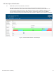
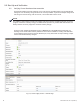
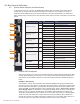
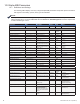
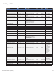
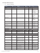
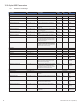
Table Of Contents
- Table 1-1, DSM3 Series Model Specifications
- Table 2-1, LEDs and Indications
- Table 3-1, Modem Community String Parameters — DOCSIS 2.0 (IPv4) Method
- Table 3-2, Modem Community String Parameters — DOCSIS 2.0+IPv6 Method
- Table 3-3, Trap Destination Addresses — DOCSIS 2.0 (IPv4) Method
- Table 3-4, Trap Destination Addresses — DOCSIS 2.0+IPv6 Method
- Table 3-5, Default atidoc.cfg Download Settings
- Table 3-6, Communications Parameters
- Table 4-1, DSM3 Series Communications Module Security Levels
- Table 4-3, Time Offset Values and Location Reference (offset +/- GMT)
- Table 5-1, Modem Firmware Upgrade SNMP Parameters
- Table 5-2, SNMP Parameters
- Table 5-3, DOCSIS Configurations File Values
- Table 6-1, SCTE-HMS MIB Files
- Table 6-2, Binary to Hex Conversions for Alarm Settings
- Table 6-3, Recommended Settings for DSM3 Series Analog Alarms
- Table 6-4, Recommended Settings for Discrete Alarms
- Table 6-5, DSM Alarm Setting Paramters
- Table 6-6, Status of Alarm Setting Download Parameters
- Table 6-7, SNMP Alarm Trap Varbinds and Explanations
- Table 6-8, Power Alarms: Classifications, Causes and Corrections
- Table 6-9, Battery Alarms: Classifications, Causes and Corrections
- Table 6-9, Alpha MIB Hierarchy
- Table 6-10, Alpha MIBs Examples
- Table 7-1, Tamper (TPR) Switch Specifications
- Table 7-2, ENV Connector and Pin Descriptions
- Table 7-3, I/O Port Specifications
- Table 7-4, I/O Port: Generic Device Specifications
- Table 7-5, LA-P-SM Monitoring Values
- Table 7-6, I/O Port: Heater Mat Control Specifications
- Table 7-7, Heater Mat OIDs and Functionality
- Table 7-8, Heater Mat MIB Reports
- Table 7-9, Generator Monitoring Values
- Table 9-1,SCTE-HMS Property Table
- Table 9-2, Rx/Tx Power LED Color Ranges
- Table 13-1, Single IP Mode versus Dual IP Mode
- Table 13-2, Enabling Dual IP mode
- Table 13-3, CPE Communications Module IP Settings
- Table 13-4, Available Download Options
- 1.0 Introduction
- 2.0 Overview
- 3.0 Network Configuration
- 3.1 Provisioning the DHCP Server with the MAC Addresses
- 3.2 Establishing IP Connectivity
- 3.3 The DOCSIS Configuration File
- 3.3.8 Changing Default atidoc03.cfg Download Settings
- 3.3.7 Proprietary Configuration File ‘atidoc03.cfg’
- 3.3.6 Sample DOCSIS Configuration File Entries — DOCSIS 2.0+IPv6
- 3.3.5 Sample DOCSIS Configuration File Entries — DOCSIS 2.0 (IPv4)
- 3.3.4 Setting SNMP Trap Destination Addresses — DOCSIS 2.0+IPv6 Method
- 3.3.3 Setting SNMP Trap Destination Addresses — DOCSIS 2.0 (IPv4) Method
- 3.3.2 Setting Modem Community Strings — DOCSIS 2.0+IPv6 Method
- 3.4 Setting Communication Options
- 4.0 Web Interface
- 4.1 Local Web Server Access
- 4.2 Remote Web Server Access
- 4.3 Navigating the Web Page
- 4.4 Verifying Communication Parameters
- 4.5 Verifying Power Supply and Battery Parameters
- 4.6 Remote Self Tests via the Web Page
- 4.7 Viewing HMS Alarm Status via the Web Page
- 4.8 Setting the I/O Controller via the Web Page
- 4.9 Viewing and Configuring Power Supply settings via the Web Page
- 4.10 Viewing and Configuring Generator Settings via the Web Page
- 4.11 Tools Menu – Constellation and Microreflections
- 4.12 Viewing AlphaApps Information via the Web Page
- 4.13 Battery Management
- 4.14 Viewing Power Supply Event and Configuration Logs
- 4.15 Battery Event Log
- 4.16 Viewing the Modem Event Log via the Web Page
- 5.0 Upgrading Firmware
- 6.0 Data Management
- 7.0 Installation
- 7.1 Verifying Power Supply Device Address
- 7.2 Installation / Replacement Procedure in XM3 Power Supplies
- 7.3 DSM3x LEDs and Connections
- 7.4 DSM3 LEDs and Connections
- 7.5 DPM LEDs and Connections
- 7.6 Connecting the RF Drop
- 7.7 Front Panel Connections
- 7.8 I/O Connections (TPR, ENV)
- 7.8.1 Tamper (TPR) Switch Interface
- 7.8.2 I/O Port Interface
- 7.8.3 Configuring I/O Port Connections
- 7.8.4 I/O Port: Generic Device
- 7.8.5 Connecting a Generic I/O Device
- 7.8.6 Configuring and Monitoring a Generic I/O Device
- 7.8.7 I/O Port: Lightning Arrestor (LA-P-SM)
- 7.8.8 Lightning Arrestor (LA-P-SM) Installation
- 7.8.9 Configuring the LA-P-SM
- 7.8.10 I/O Port: Heater Mat Control
- 7.8.11 Connecting the Battery Heater Mat Controller, continued
- 7.8.12 Configuring the Battery Heater Mat Controller
- 7.8.14 Configuring and Monitoring the DC Emergency Generator
- 8.0 Battery Sense Wire Kits
- 9.0 Start Up and Verification
- 10.0 Alpha MIB Parameters
- 11.0 Specifications
- 12.0 Glossary
- 13.0 Dual IP Mode (Addendum)
- 13.1 Overview
- 13.2 Web Comparison, Single IP Mode/Dual IP Mode
- 13.3 Configuring Dual IP Mode
- 13.3.3 Specifying atidoc03.cfg name and location via DHCP Tags
- 13.3.2 Changing Default atidoc03.cfg Download Settings in Dual IP Mode
- 13.3.1 atidoc03.cfg in Dual IP Mode
- 13.4 Dual IP SNMP Community Strings
- 13.5 Security in Dual IP Mode
- Fig. 1-1, AlphaNet DSM3x
- Fig. 1-2, AlphaNet DSM3
- Fig. 1-3, AlphaNet DPM
- Fig. 1-4, Side view, AlphaNet DSM3 Series
- Fig. 2-1, Representative System Arrangement
- Fig. 3-1, Locations of MAC Address Labels
- Fig. 3-2, Sample DOCSIS Configuration File — DOCSIS 2.0 (IPv4)
- Fig. 3-3, Sample DOCSIS Configuration File — DOCSIS 2.0+IPv6
- Fig. 4-1, DSM3 Series Web Page
- Fig. 4-2, Local Area Connection Properties Screen, Windows XP
- Fig. 4-3, Internet Protocol (TCP/IP) Properties Screen, Windows XP
- Fig. 4-4, Local Area Connection Properties Screen, Windows 7
- Fig. 4-5, Internet Protocol (TCP/IP) Properties Screen, Windows 7
- Fig. 4-6, Web Server Home Page
- Fig. 4-7, DSM3 Series Navigation Bar Items
- Fig. 4-8, Communication Parameters
- Fig. 4-9, Advanced Communication Parameters
- Fig. 4-10, Power Supply and Battery Parameters
- Fig. 4-11, Location of Start Test Button for Self Test
- Fig. 4-12, HMS Alarm Configuration
- Fig. 4-13, Advanced I/O Controller Status Screen
- Fig. 4-14, Advanced Power Supply Settings Screen
- Fig. 4-15, Advanced Generator Status Screen
- Fig. 4-16, QAM Constellation Tool
- Fig. 4-17, Normal - (Good Quality) and Individual Cell Characteristics
- Fig. 4-18, Fuzzy (Low CNR and/or Low MER) and Individual Cell Characteristics
- Fig. 4-19, Doughnuts (Coherent Interference) and Individual Cell Characteristics
- Fig. 4-20, Gaussian Noise and Individual Cell Characteristics
- Fig. 4-21, Rectangular vs. Square (I-Q Imbalance) and Entire Constellation Shape
- Fig. 4-22, Corners Squeezed to Center (Gain Compression) and Entire Constellation Shape
- Fig. 4-23, Circular Smear (Phase Noise) and Entire Constellation Shape
- Fig. 4-24, Twisted or Skewed (Quadrature Distortion) and Entire Constellation Shape
- Fig. 4-25, Microreflections Tool
- Fig. 4-26, Alpha Apps and Utility Status Parameters
- Fig. 4-27, Battery Management
- Fig. 4-28, Battery Model Selection
- Fig. 4-29, DSM3 System Log
- Fig. 4-30, Power Supply Event Log
- Fig. 4-31, Power Supply Configuration Log
- Fig. 4-33, Docsdev Event Log Screen
- Fig. 6-1, Sample Raw SNMP Alarm Trap
- Fig. 6-2, Sample Translated SNMP Alarm Trap
- Fig. 7-1, Captive Screw Locations
- Fig. 7-3, Connecting the Communications Module to the Inverter Module
- Fig. 7-2, The 18-pin Connector
- Fig. 7-4, DSM3x LEDs and Connectors
- Fig. 7-5, DSM3 LEDs and Connectors
- Fig. 7-6, DPM LEDs and Connectors
- Fig. 7-7, Connecting the RF Drop
- Fig. 7-8, System Interconnection Diagram
- Fig. 7-9, I/O (ENV) and Tamper Switch Interface (TPR) Connection Locations
- Fig. 8-1, 36V System, Single String
- Fig. 8-2, 36V System, Dual String
- Fig. 9-1, XM3 Smart Display Screens
- Fig. 9-2, Communications Section - General Page
- Fig. 9-3, Power Supply Section - General Page
- Fig. 9-4, LED Functionality and Indications
- Fig. 9-5, DSM3 Series Web Page, RF Power Level Indicators
- Fig. 13-1, Simplified Block Diagram Single IP Mode
- Fig 13-2, Simplified Block Diagram Dual IP Mode
- Fig. 13-3, Single IP DSM3 Series Web Page
- Fig. 13-4, Dual IP DSM3 Series Web Page
- Fig. 13-5, Dual IP Configuration Settings for DSM3 Web Server Communications Page
- Fig. 13-6, Dual IP Parameters for DSM3 Web Server General Page

90
745-814-B11-001, Rev. C (03/2014)
Parameter OID Description Access Type Value
COUNTERS
atiBBSysViewCounters 1.3.6.1.4.1.926.1.4.1.1.4 Object Identier
atiBBSysViewSelfTestInterval 1.3.6.1.4.1.926.1.4.1.1.4.1 Number of days between automated Self Tests Read-Write Integer 0..65535
atiBBSysViewSelfTestCountdown 1.3.6.1.4.1.926.1.4.1.1.4.2 Number of days until the next automated Self Test Read-Write Integer 0..65535
atiBBSysViewSelfTestDuration 1.3.6.1.4.1.926.1.4.1.1.4.3 Number of minutes for which an automated Self
Test will run
Read-Write Integer 0..65535
atiBBSysViewInverterRuntime 1.3.6.1.4.1.926.1.4.1.1.4.4 Number of minutes the inverter has run due to an
AC fail event
Read Only Integer 0..65535
atiBBSysViewStandbyEvents 1.3.6.1.4.1.926.1.4.1.1.4.5 Number of times the inverter has gone into standby
due to an AC fail event
Read Only Integer 0..65535
atiBBSysViewRuntimeRemaining 1.3.6.1.4.1.926.1.4.1.1.4.6 Seconds of estimated runtime remaining when in
standby
Read Only Integer 0..65535
atiBBSysViewTimeInStandby 1.3.6.1.4.1.926.1.4.1.1.4.7 Seconds. If currently in standby, time in standby. If
not in standby this value will be zero
Read Only Integer 0..-1
atiBBSysViewTimeSinceLastStandby 1.3.6.1.4.1.926.1.4.1.1.4.8 Seconds. The accumulated time since the end of
last standby event and the start of the next standby
event. The counter will reset to zero after the next
standby event has ended.
Read Only Integer 0..-1
atiBBSysViewTimeInLastStandby 1.3.6.1.4.1.926.1.4.1.1.4.9 Seconds. The length (time) of last standby event.
If currently in a standby event this value will be the
length of the previous standby event. This value will
be updated at the conclusion of each standby event.
This item is saved in non-vol memory.
Read Only Integer 0..-1
PLATFORMS
atiProductPlatforms 1.3.6.1.4.1.926.1.4 Object Identier
atiBroadbandUPS 1.3.6.1.4.1.926.1.4.1 Object Identier
atiBBSysView 1.3.6.1.4.1.926.1.4.1.1 Object Identier
atiBBSysViewSelects 1.3.6.1.4.1.926.1.4.1.1.1 Object Identier
atiBBSysViewSelfTestControl 1.3.6.1.4.1.926.1.4.1.1.1.1.0 Starts/Stops a system Self Test Read/Write Integer 1=Stop
2=Start
atiBBSysViewSelfTestInhibit 1.3.6.1.4.1.926.1.4.1.1.1.2.0 System Self Test is prevented. On reset, the DSM
gets this value from the master XM3 (in a system
with more than one power supply).
Read/Write Integer 1=Normal (default)
2=Inhibited
atiBBSysViewSystemControlMgr 1.3.6.1.4.1.926.1.4.1.1.1.3.0 If the System Control Manager is running, the Small
System Controller/Administrator (SSC or SSA)
is running and there is coordination between the
power supplies for charging, testing, etc. The value
of this item is stored in non-volatile memory.
Read/Write Integer 1=Running
2=Disabled
SYSTEM ALARMS
atiBBSysViewAlarms 1.3.6.1.4.1.926.1.4.1.1.2 Object Identier
atiBBSysViewMajorAlarm 1.3.6.1.4.1.926.1.4.1.1.2.1.0 Indicates if any of the items monitored are in a major
alarm state
Read Only Integer 1=OK
2=Alarm
atiBBSysViewMinorAlarm 1.3.6.1.4.1.926.1.4.1.1.2.2.0 Indicates if any of the items monitored are in a minor
alarm state
Read Only Integer 1=OK
2=Alarm
atiBBSysViewSelfTestResult 1.3.6.1.4.1.926.1.4.1.1.2.3.0 If any of the items being monitored indicate that Self
Test failed, this item indicates a failure.
Read Only Integer 1=OK
2=Fail
atiBBSysViewTempProbeStatus 1.3.6.1.4.1.926.1.4.1.1.2.4.0 If any of the devices being monitored indicate a
temp probe failure or absence, this item will alarm.
Read Only Integer 1=OK
2=Missing
atiBBSysViewInputStatus 1.3.6.1.4.1.926.1.4.1.1.2.5.0 If ALL the items being monitored indicate no AC, this
item will alarm.
Read Only Integer 1=OK
2=No AC Present
10.1 Denitions and Settings
10.0 Alpha MIB Parameters