
Manual
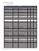
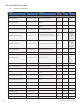
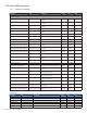
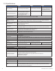
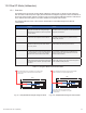
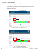
Table Of Contents
- Table 1-1, DSM3 Series Model Specifications
- Table 2-1, LEDs and Indications
- Table 3-1, Modem Community String Parameters — DOCSIS 2.0 (IPv4) Method
- Table 3-2, Modem Community String Parameters — DOCSIS 2.0+IPv6 Method
- Table 3-3, Trap Destination Addresses — DOCSIS 2.0 (IPv4) Method
- Table 3-4, Trap Destination Addresses — DOCSIS 2.0+IPv6 Method
- Table 3-5, Default atidoc.cfg Download Settings
- Table 3-6, Communications Parameters
- Table 4-1, DSM3 Series Communications Module Security Levels
- Table 4-3, Time Offset Values and Location Reference (offset +/- GMT)
- Table 5-1, Modem Firmware Upgrade SNMP Parameters
- Table 5-2, SNMP Parameters
- Table 5-3, DOCSIS Configurations File Values
- Table 6-1, SCTE-HMS MIB Files
- Table 6-2, Binary to Hex Conversions for Alarm Settings
- Table 6-3, Recommended Settings for DSM3 Series Analog Alarms
- Table 6-4, Recommended Settings for Discrete Alarms
- Table 6-5, DSM Alarm Setting Paramters
- Table 6-6, Status of Alarm Setting Download Parameters
- Table 6-7, SNMP Alarm Trap Varbinds and Explanations
- Table 6-8, Power Alarms: Classifications, Causes and Corrections
- Table 6-9, Battery Alarms: Classifications, Causes and Corrections
- Table 6-9, Alpha MIB Hierarchy
- Table 6-10, Alpha MIBs Examples
- Table 7-1, Tamper (TPR) Switch Specifications
- Table 7-2, ENV Connector and Pin Descriptions
- Table 7-3, I/O Port Specifications
- Table 7-4, I/O Port: Generic Device Specifications
- Table 7-5, LA-P-SM Monitoring Values
- Table 7-6, I/O Port: Heater Mat Control Specifications
- Table 7-7, Heater Mat OIDs and Functionality
- Table 7-8, Heater Mat MIB Reports
- Table 7-9, Generator Monitoring Values
- Table 9-1,SCTE-HMS Property Table
- Table 9-2, Rx/Tx Power LED Color Ranges
- Table 13-1, Single IP Mode versus Dual IP Mode
- Table 13-2, Enabling Dual IP mode
- Table 13-3, CPE Communications Module IP Settings
- Table 13-4, Available Download Options
- 1.0 Introduction
- 2.0 Overview
- 3.0 Network Configuration
- 3.1 Provisioning the DHCP Server with the MAC Addresses
- 3.2 Establishing IP Connectivity
- 3.3 The DOCSIS Configuration File
- 3.3.8 Changing Default atidoc03.cfg Download Settings
- 3.3.7 Proprietary Configuration File ‘atidoc03.cfg’
- 3.3.6 Sample DOCSIS Configuration File Entries — DOCSIS 2.0+IPv6
- 3.3.5 Sample DOCSIS Configuration File Entries — DOCSIS 2.0 (IPv4)
- 3.3.4 Setting SNMP Trap Destination Addresses — DOCSIS 2.0+IPv6 Method
- 3.3.3 Setting SNMP Trap Destination Addresses — DOCSIS 2.0 (IPv4) Method
- 3.3.2 Setting Modem Community Strings — DOCSIS 2.0+IPv6 Method
- 3.4 Setting Communication Options
- 4.0 Web Interface
- 4.1 Local Web Server Access
- 4.2 Remote Web Server Access
- 4.3 Navigating the Web Page
- 4.4 Verifying Communication Parameters
- 4.5 Verifying Power Supply and Battery Parameters
- 4.6 Remote Self Tests via the Web Page
- 4.7 Viewing HMS Alarm Status via the Web Page
- 4.8 Setting the I/O Controller via the Web Page
- 4.9 Viewing and Configuring Power Supply settings via the Web Page
- 4.10 Viewing and Configuring Generator Settings via the Web Page
- 4.11 Tools Menu – Constellation and Microreflections
- 4.12 Viewing AlphaApps Information via the Web Page
- 4.13 Battery Management
- 4.14 Viewing Power Supply Event and Configuration Logs
- 4.15 Battery Event Log
- 4.16 Viewing the Modem Event Log via the Web Page
- 5.0 Upgrading Firmware
- 6.0 Data Management
- 7.0 Installation
- 7.1 Verifying Power Supply Device Address
- 7.2 Installation / Replacement Procedure in XM3 Power Supplies
- 7.3 DSM3x LEDs and Connections
- 7.4 DSM3 LEDs and Connections
- 7.5 DPM LEDs and Connections
- 7.6 Connecting the RF Drop
- 7.7 Front Panel Connections
- 7.8 I/O Connections (TPR, ENV)
- 7.8.1 Tamper (TPR) Switch Interface
- 7.8.2 I/O Port Interface
- 7.8.3 Configuring I/O Port Connections
- 7.8.4 I/O Port: Generic Device
- 7.8.5 Connecting a Generic I/O Device
- 7.8.6 Configuring and Monitoring a Generic I/O Device
- 7.8.7 I/O Port: Lightning Arrestor (LA-P-SM)
- 7.8.8 Lightning Arrestor (LA-P-SM) Installation
- 7.8.9 Configuring the LA-P-SM
- 7.8.10 I/O Port: Heater Mat Control
- 7.8.11 Connecting the Battery Heater Mat Controller, continued
- 7.8.12 Configuring the Battery Heater Mat Controller
- 7.8.14 Configuring and Monitoring the DC Emergency Generator
- 8.0 Battery Sense Wire Kits
- 9.0 Start Up and Verification
- 10.0 Alpha MIB Parameters
- 11.0 Specifications
- 12.0 Glossary
- 13.0 Dual IP Mode (Addendum)
- 13.1 Overview
- 13.2 Web Comparison, Single IP Mode/Dual IP Mode
- 13.3 Configuring Dual IP Mode
- 13.3.3 Specifying atidoc03.cfg name and location via DHCP Tags
- 13.3.2 Changing Default atidoc03.cfg Download Settings in Dual IP Mode
- 13.3.1 atidoc03.cfg in Dual IP Mode
- 13.4 Dual IP SNMP Community Strings
- 13.5 Security in Dual IP Mode
- Fig. 1-1, AlphaNet DSM3x
- Fig. 1-2, AlphaNet DSM3
- Fig. 1-3, AlphaNet DPM
- Fig. 1-4, Side view, AlphaNet DSM3 Series
- Fig. 2-1, Representative System Arrangement
- Fig. 3-1, Locations of MAC Address Labels
- Fig. 3-2, Sample DOCSIS Configuration File — DOCSIS 2.0 (IPv4)
- Fig. 3-3, Sample DOCSIS Configuration File — DOCSIS 2.0+IPv6
- Fig. 4-1, DSM3 Series Web Page
- Fig. 4-2, Local Area Connection Properties Screen, Windows XP
- Fig. 4-3, Internet Protocol (TCP/IP) Properties Screen, Windows XP
- Fig. 4-4, Local Area Connection Properties Screen, Windows 7
- Fig. 4-5, Internet Protocol (TCP/IP) Properties Screen, Windows 7
- Fig. 4-6, Web Server Home Page
- Fig. 4-7, DSM3 Series Navigation Bar Items
- Fig. 4-8, Communication Parameters
- Fig. 4-9, Advanced Communication Parameters
- Fig. 4-10, Power Supply and Battery Parameters
- Fig. 4-11, Location of Start Test Button for Self Test
- Fig. 4-12, HMS Alarm Configuration
- Fig. 4-13, Advanced I/O Controller Status Screen
- Fig. 4-14, Advanced Power Supply Settings Screen
- Fig. 4-15, Advanced Generator Status Screen
- Fig. 4-16, QAM Constellation Tool
- Fig. 4-17, Normal - (Good Quality) and Individual Cell Characteristics
- Fig. 4-18, Fuzzy (Low CNR and/or Low MER) and Individual Cell Characteristics
- Fig. 4-19, Doughnuts (Coherent Interference) and Individual Cell Characteristics
- Fig. 4-20, Gaussian Noise and Individual Cell Characteristics
- Fig. 4-21, Rectangular vs. Square (I-Q Imbalance) and Entire Constellation Shape
- Fig. 4-22, Corners Squeezed to Center (Gain Compression) and Entire Constellation Shape
- Fig. 4-23, Circular Smear (Phase Noise) and Entire Constellation Shape
- Fig. 4-24, Twisted or Skewed (Quadrature Distortion) and Entire Constellation Shape
- Fig. 4-25, Microreflections Tool
- Fig. 4-26, Alpha Apps and Utility Status Parameters
- Fig. 4-27, Battery Management
- Fig. 4-28, Battery Model Selection
- Fig. 4-29, DSM3 System Log
- Fig. 4-30, Power Supply Event Log
- Fig. 4-31, Power Supply Configuration Log
- Fig. 4-33, Docsdev Event Log Screen
- Fig. 6-1, Sample Raw SNMP Alarm Trap
- Fig. 6-2, Sample Translated SNMP Alarm Trap
- Fig. 7-1, Captive Screw Locations
- Fig. 7-3, Connecting the Communications Module to the Inverter Module
- Fig. 7-2, The 18-pin Connector
- Fig. 7-4, DSM3x LEDs and Connectors
- Fig. 7-5, DSM3 LEDs and Connectors
- Fig. 7-6, DPM LEDs and Connectors
- Fig. 7-7, Connecting the RF Drop
- Fig. 7-8, System Interconnection Diagram
- Fig. 7-9, I/O (ENV) and Tamper Switch Interface (TPR) Connection Locations
- Fig. 8-1, 36V System, Single String
- Fig. 8-2, 36V System, Dual String
- Fig. 9-1, XM3 Smart Display Screens
- Fig. 9-2, Communications Section - General Page
- Fig. 9-3, Power Supply Section - General Page
- Fig. 9-4, LED Functionality and Indications
- Fig. 9-5, DSM3 Series Web Page, RF Power Level Indicators
- Fig. 13-1, Simplified Block Diagram Single IP Mode
- Fig 13-2, Simplified Block Diagram Dual IP Mode
- Fig. 13-3, Single IP DSM3 Series Web Page
- Fig. 13-4, Dual IP DSM3 Series Web Page
- Fig. 13-5, Dual IP Configuration Settings for DSM3 Web Server Communications Page
- Fig. 13-6, Dual IP Parameters for DSM3 Web Server General Page

95745-814-B11-001, Rev. C (03/2014)
DSM3x DSM3 DPM
Power Supply Monitored Parameters
Major Alarm:
Aggregate alarm consisting of: Test fail, battery fail, line isolation alarm, output overload, inverter,
over-temperature, N+1 active, fuse fail
Minor Alarm: Aggregate alarm consisting of: Temperature probe error, AC line loss, N+1 error
Input Voltage: Reported from power supply V(in) measurement
Output Voltage: Reported from power supply V(out) measurement
Output Current:
0 to 25A standard on port 1
Port 2 requires power suppy DOC option
Output Power: Calculated; reported in AC Watts
Input Current: Reported in Amps
Input Power: Reported in Amps
UPS Status: AC Line, Standby, Test in progress, Test alarm
Charger Current: Reported in Amps
Battery Discharge Current: Reported in Amps
Enclosure Door: Open or Closed
Battery Voltage:
Individual battery voltage, up
to four strings of 3 batteries
(maximum 12 batteries),
±100mV per battery.
Individual battery voltage,
up to two strings of 3
batteries (maximum 6
batteries), ±100mV per
battery.
Individual battery voltage, up to
four strings of 3 batteries
(maximum 12 batteries),
±100mV per battery.
(Requires SAG option)
Battery Temperature: Reported from power supply battery Remote Temperature Sensor (RTS)
Remote Test Control: Start/Stop power supply test cycle
Generator Monitored Parameters (DSM3x Only)
Status: Generator Off, Running, Alarm
Generator Alarm:
Aggregate alarm consisting of: Low oil pressure, engine over-temp, engine over-speed, crank limit,
over voltage, low fuel, water intrusion, pad shear, gas hazard, test fail
Gas Hazard: OK, Alarm
Water Intrusion: OK, Alarm
Pad Shear: OK, Alarm
Enclosure Door: OK, Alarm
Ignition Battery Voltage: Reported in DC volts, ±100mV
Enclosure Temperature: Reported in Celcius, ±2°C
Low Fuel: OK, Alarm
Remote Test Control: Start / Stop generator test cycle
Cable Modem
Compliance: DOCSIS 1.1 and 2.0 EuroDOCSIS 2.0
Transmit Frequency Range: 5 to 42 MHz 5 to 65 Mhz
Receive Center Frequency Range: 91 to 857 MHz 112 to 858 Mhz
Output Power Range:
TDMA:
+8 to +54 dBmV (32QAM, 64QAM)
+8 to +55 dBmV (8QAM, 16QAM)
+8 to +58 dBmV (QPSK)
S-CDMA:
+8 to +53 dBmV (All modulations of S-CDMA)
TDMA:
+68 to +114 dBuV (32QAM, 64QAM)
+68 to +115 dBuV (8QAM, 16QAM)
+68 to +118 dBuV (QPSK)
S-CDMA:
+68 to +113 dBuV (All modulations of S-CDMA)
Input Signal Range: -15 to 15 dBmV
64QAM: 43 to 73 dBuV
256QAM: 47 to 77 dBuV
Channel Bandwidth: 6 MHz 8 Mhz
Additional Equipment
874-842-21 XP-BSC-3-6: Wire Kit, Battery Sense, 1x36V, 6'
874-842-20 XP-BSC-6-6: Wire Kit, Battery Sense, 2x36V, 6'
Surge Arrestor
(Alpha p/n 162-028-10):
Female/Female connector conguration, “F” type connector with integral ground block. Required for
all installations
11.0 Specications