
Quick Start Guide Manual

1746-114-B5-001 Rev. B (04/2013)
AlphaNet
™
DSM3 Series DOCSIS
®
Status Monitor
for the XM3 CableUPS
®
Installation and Quick Start Guide
The AlphaNet DSM3 Series (DSM3, DSM3x, DPM models) Embedded DOCSIS Communications Module allows monitoring of Alpha power
supplies through existing cable network infrastructure. Advanced networking services provide quick reporting and access to critical powering
information.
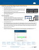
DSM3 Series Communications Modules utilize Simple Network Management Protocol (SNMP) and Management Information Bases (MIBs) to
provide network status monitoring and diagnostics. A Web interface enables authorized personnel direct local and remote access to advanced
diagnostics using a common Web browser. No proprietary cables or software are required.
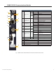
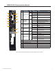
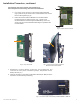
The Communications Modules can be installed and congured for operation in the XM3-HP CableUPS
®
Power Supply. The major features of
the DSM3x are shown below; the DSM3 and the DPM models are shown on the following pages.
12
13
14
15
7
8
10
16
17
18
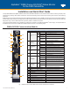
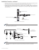
DSM3x DOCSIS Communications Module
Fig. 1, DSM3x Communications Module Front Panel Indicators and Connectors
Item LED or Connector Status Behavior Indication
1
ALM/RDY: Alarm and
Ready
N/A OFF No power or malfunctioning DSM3 Series
GRN
ON Reset of the DSM3 Series is in process
Steady Blinking Normal operation
RED
Blinking more
OFF than ON
Minor Alarm
Blinking more
ON than OFF
Major Alarm
2
REG: Upstream
ranging and
registration lock
GRN
OFF No power, upstream frequency undetermined
Blinking
Power on, downstream locked, upstream frequency ranging,
DHCP request in progress
ON CMTS registration completed
3
DS: Downstream
RF Carrier detection
and lock
GRN
OFF No power / downstream carrier
Blinking Power on, downstream carrier frequency searching
ON Downstream carrier lock
4
ACT: CPE Activity
status
GRN
OFF No Ethernet communications activity
Blinking
Momentary ashes during CPE communications via the
Ethernet craft port
5
LNK: CPE Link
status
GRN
OFF No Ethernet link
ON Link on Ethernet Craft port
6
RF Rx/Tx Power
Level Indicator
TRI
OFF No RF detected
Blue
Rx/Tx Power at a warning level as set within the SCTE-HMS
Property Table
Green Rx/Tx RF Power level within tolerance
Red
Rx/Tx Power at an alert level as set within the SCTE-HMS
Property Table
7
COM: AlphaBus
communications
GRN
OFF No AlphaBus Communications
Blinking Momentary ashes - AlphaBus Port communications active
8 BAT A/B GRN ON/OFF ON (steady) if battery string(s) connected correctly
9 BAT A/B Connector
10 BAT C/D GRN ON/OFF ON (steady) if battery string(s) connected correctly
11 BAT C/D Connector
12 RST: Reset Buttton
13 ENV: Environmental Control Connector
14 TPR: Tamper Switch Connector
15 ETH: Ethernet Connector
16 RF Connector
17 COM: AlphaBus Communications Connector
18 CM, CPE MAC Address Label
9
11
1
2
3
4
5
6