
Quick Start Guide Manual

4746-114-B5-001 Rev. B (04/2013)
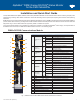
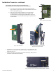
Fig. 3, XM3-HP with DSM3x Communications Module Installed
Service personnel must verify the Inverter Module battery breaker remains in the OFF position until instructed to
return unit to service.
CAUTION!
For units in service, backup battery power will not be available during this procedure.
CAUTION!
Overview
DSM3 Series installation and setup is comprised of three basic steps:
1. Installation of the DSM3 Series into the power supply, making front panel connections and verifying operation.
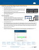
2. Setting Options: the DSM3 Series is designed for out-of-the-box, "plug and play" operation. Non-default settings such as
SNMP trap destination addresses may be required for the Network Management System (NMS). SNMP trap addresses
can be set automatically via the DOCSIS conguration le's docsDevNmAccessTable per RFC 4639 (IPv4) or through
the SNMPv3 Notication settings (IPv6), while DSM3 Series proprietary options may be set through type 11 TLV entries.
The SCTE-HMS and Alpha MIBs may need to be compiled into a MIB browser before it can be used to monitor or set
transponder and power supply parameters. Refer to the DSM3 Series Technical Manual for details.
3. Conguring the Network: provisioning the DHCP Server with the transponder’s MAC address and assigning it a
DOCSIS conguration le.
These steps can be performed independently of one another. However, conguring the network prior to eld installation will
allow the installation to be veried while personnel are still on-site. Performing eld installation before network conguration
might result in additional eld service calls to correct mistakes.
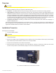
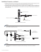
Removing the Inverter Module:
1. Turn off the battery breaker.
Installation Procedure
2. Disconnect the battery input and temperature sensor cables from the Inverter Module and the tamper, RF and battery
sense cables from the communication module if one is currently installed.
3. Loosen the two thumbscrews on the XM3 Inverter Module.
4. Grasp the handle on the bottom right side of the Inverter Module. Pull rmly to release the module from the inverter
connector. Gently slide the module assembly straight out until the Inverter Module is accessible.