EDSM Enhanced Digital Status Module Technical Manual Enhanced Digital Status Module Effective: May 2008 Alpha Technologies
Alpha Technologies Power ®
Enhanced Digital Status Module Technical Manual 704-721-C0-004, Rev. D Effective Date: May 2008 Copyright© 2008 Alpha Technologies, Inc. member of The GroupTM NOTE: Photographs contained in this manual are for illustrative purposes only. These photographs may not match your installation. NOTE: Operator is cautioned to review the drawings and illustrations contained in this manual before proceeding.
Table of Contents Safety Notes .......................................................................................................................... 6 1.0 Introduction ................................................................................................................. 8 1.1 2.0 3.0 Connectors and Indicators ........................................................................................ 10 2.1 LED Indicators .....................................................................
List of Figures and Tables Fig. 1-1, Enhanced Digital Status Module ............................................................................. 8 Fig. 1-2, Power System Interconnection................................................................................ 9 Fig. 2-1, LED Arrangement .................................................................................................. 10 Fig. 2-2, COM Connector ...........................................................................................
Safety Notes Review the drawings and illustrations contained in this manual before proceeding. If there are any questions regarding the safe installation or operation of this product, contact Alpha Technologies or the nearest Alpha representative. Save this document for future reference. To reduce the risk of injury or death, and to ensure the continued safe operation of this product, the following symbols have been placed throughout this manual. Where these symbols appear, use extra care and attention.
General Safety Precautions To avoid injury: • This enclosure and its associated hardware must be serviced only by authorized personnel. • Enclosure must remain locked at all times, except when authorized service personnel are present. • Remove all conductive jewelry or personal equipment prior to servicing equipment, parts, connectors, wiring, or batteries. • Read and follow all installation, equipment grounding, usage, and service instructions included in this manual.
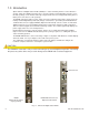
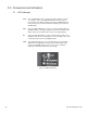
1.0 Introduction Alpha’s Enhanced Digital Status Module (EDSM) is a status monitoring interface for the XM Series 2 power supply. The EDSM can monitor up to six power supplies and an AlphaGen generator. Up to two battery strings can be monitored directly using the AUX connector and applicable wiring harness. Battery Sense wire kits are sold separately. The EDSM continuously gathers power supply, generator, and battery data.
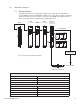
1.0 Introduction, continued 1.1 System Layout The diagram below shows a typical power supply system using either an embedded or external digital transponder.The EDSM can monitor up to six (6) power supplies, two battery strings via the AUX connector, and one (1) generator. The EDSM collects data from these devices and relays it to the head end using a digital transponder.
2.0 Connectors and Indicators 2.1 LED Indicators ALM The red ALM LED reflects system level alarms. When a system level alarm is active, the ALM LED will flash. A major alarm is present when the LED is flashing faster than the READY LED. A minor alarm is present when the LED is flashing slower than the READY LED. RDY The green RDY LED flashes once per second to indicate that the EDSM software is running normally. Under normal conditions, this LED is only turned off while alarm codes are being displayed.
2.0 Connectors and Indicators, continued 2.2 STAT Switch The momentary push-button labeled "STAT" on the front panel has two functions. When held down MORE than 3 seconds, the microcontroller will reset. If held down LESS than 2 seconds, the LED matrix will display any faults being reported to the microcontroller. Repeated presses of the STAT button will display subsequent alarms. The table below lists all of the valid error codes. Display Alarm Definition ALM/RDY Reserved This code is not used.
2.0 Connectors and Indicators, continued 2.3 COM Connector The COM connector is used to communicate with the other devices in the power system (i.e. the AlphaGuard CMM, XM2-SI card). The DT connector can connect the EDSM to an external digital transponder. Pin # Description 1 Sys Com Pwr (+) 2&5 RS-485 (+) 3&4 RS-485 (-) 6 Sys Com Pwr (-) Fig. 2-2, COM Connector Fig. 2-3, DT Connector CAUTION! The DT connector is only used for connecting to an external digital transponder.
2.0 Connectors and Indicators, continued 2.4 AUX and Tamper Connectors The AUX connector allows the EDSM to monitor two 36Vdc or 48Vdc battery strings. The TAMPER connector is used for cabinet door detection. Tamper switches are wired in parallel and connected at this location.
2.0 Connectors and Indicators, continued 2.5 DIP Switch The on board DIP Switch (SW2) is used to configure the tamper polarity, provide RS-485 biasing per the ANSI/SCTE25-3 Specification, and to enable programming. The factory default switch settings are in the OFF position, with the exception of #3 in the ON position. The tamper polarity switch allows for either a N/O or N/C switch to be used for enclosure door monitoring.
2.0 Connectors and Indicators, continued 2.6 Headers The OEM Embedded Transponder (OEMET) connector is located in the lower right hand corner of the circuit board and uses a 2x5 ribbon cable connector. The connector is used for connecting the EDSM to a digital transponder.
3.0 Module Installation NOTE: • If the XMS2 system already has an existing comm module installed, remove the module as outlined in the procedure below. If the system does not have a communications module installed, proceed to the next section for the installation procedure. • During this procedure, backup capability will be temporarily lost. 3.1 XMS2 Communication Module Removal Procedure Allow 15 minutes for completion of procedure Tools required: #2 Phillips screwdriver 1.
3.0 Module Installation, continued 3.1 XMS2 Communication Module Removal Procedure, continued 7. Slide the inverter module out of the power supply. 8. Unscrew the captive mounting screws holding the existing comm module onto the inverter module sheet metal. 9. Verify that the 2x9 pin jumper is in position, seated fully into the inverter module. 10. Align the XMS2 header on the EDSM with the 2x9 jumper and gently press into place. 11. Tighten the captive mounting screws into the inverter module.
3.0 Module Installation, continued 3.1 XMS2 Communication Module Removal Procedure, continued 12. Slide the inverter module sheet metal into the card guides of the power supply and reconnect the ribbon cable to the connector and latch the locking pins. 13. Using ONLY the handle on the front of the inverter module, firmly seat the inverter module into the power supply and tighten the thumb screws. 14. Verify that the BATTERY BREAKER is in the OFF position. 15.
3.0 Module Installation, continued 3.1 XMS2 Communication Module Removal Procedure, continued 19. Press and hold the STAT push-button on the front panel of the EDSM until all LEDs go out, continue to press the button until the RDY LED is lit indicating that the reset function is initiated. A reset will force the EDSM to "ping" all devices in the system. 20. Place a magnet over the tamper sensor to override the Tamper Alarm. 21.
Power Alpha Technologies ® Alpha Technologies 3767 Alpha Way Bellingham, WA 98226 USA Tel: +1 360 647 2360 Fax: +1 360 671 4936 Web: www.alpha.com Alpha Technologies Ltd. 4084 McConnell Court Burnaby, BC, V5A 3N7 CANADA Tel: +1 604 430 1476 Fax: +1 604 430 8908 Alpha Technologies Europe Ltd.