FMPS FTTP Multipurpose Power Supply 010-592-B2 The following documents and drawings are included in this manual to provide the necessary information required for installation, operation and fault diagnosis of the unit: • Specifications: 010-592-B1 • Important Safety and Installation Instructions: 010-592-C0 • Warranty and Service Information: 048-700-10 • Service Centers: 048-693-10 Argus Technologies Ltd. Printed in Canada. © 2008 Argus Technologies Ltd.
Specifications for Argus Technologies’ FMPS Input Voltage (nominal): 120Vac @ 2.5A; 240Vac @ 1.25A Frequency: 50/60Hz Current (maximum): 2.5A @120Vac (maximum DC output + charger + heater) Inrush Current: 4.1A maximum (peak value) Surge Protection: ANSI/IEEE Std. C62.41 to Category A, B, or C requirements, using a “Ring Wave” or “Combination” waveform, at a level of 6kV Output Power: 150W continuous; 170W, 10 second maximum Voltage (nominal): 55Vdc Current: 3.
Specifications for Argus Technologies’ FMPS Continued Local Alarms System LED: Green steady = system output normal, DC output/off = no AC or battery power Battery LED: Yellow steady = system on battery/off = normal mode Replace Battery: Red steady = replace one or two battery strings/off = batteries within parameters Replace Battery A&B (internal): Red steady = replace one or both battery strings/off = batteries within parameters Audible Indicator (Alarm On): Alarm enable/disable toggle switch locat
Specifications for Argus Technologies’ FMPS Continued Environmental Operating Temperature: -10 to 46.
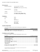
Specifications for Argus Technologies’ FMPS Continued Dimensions Battery Run Times Watts 20 40 60 80 100 120 150 ONE STRING Run Time (hours) vs. Temperature -10°C 0°C 25°C 14.4 15.6 18.7 7.0 7.4 8.9 3.9 4.8 6.6 2.7 3.1 4.3 2.2 2.5 3.2 1.8 1.9 2.6 1.5 1.7 2.0 40°C 20.0 10.0 7.2 5.5 3.7 2.9 2.3 Watts 20 40 60 80 100 120 150 TWO STRINGS Run Time (hours) vs. Temperature -10°C 0°C 25°C 21.7 22.5 24.4 14.1 15.6 18.7 9.0 9.6 13.1 6.7 7.4 8.9 5.9 6.3 7.5 3.7 4.8 6.7 3.0 3.3 5.0 40°C 25.0 20.0 15.5 10.0 7.
Specifications for Argus Technologies’ FMPS Continued Temperature Compensation Battery temperature compensation (charge voltage vs. temperature) Battery Recharge Times Battery Recharge vs. Load Power, Single String 90% Recharge Efficiency Battery Recharge vs. Load Power, Two Strings 90% Recharge Efficiency Load (W) 5 10 15 20 25 30 40 50 75 100 125 150 Load (W) 5 10 15 20 25 30 40 50 75 100 125 150 Hours 3.5 3.5 3.5 3.5 3.5 3.5 3.5 3.5 5.4 8.3 17.1 No recharge Hours 10.8 11.1 12.0 12.7 13.6 14.2 15.
SAFETY NOTES SAVE THESE INSTRUCTIONS Review the drawings and illustrations contained in this manual before proceeding. If there are any questions regarding the safe installation or operation of the system, contact Argus Technologies or your nearest Argus representative. Save this document for future reference. To reduce the risk of injury or death, and to ensure the continued safe operation of this product, the following notations/symbols have been placed throughout this manual.
General Safety Precautions To avoid injury: • Read and follow all installation, equipment grounding, usage, and service instructions included in this manual. • Disconnect power before servicing. • This enclosure and its associated hardware must be serviced only by authorized personnel. • Enclosure must remain locked at all times, except when authorized service personnel are present.
Battery Safety Notes WARNING! Lead-acid batteries contain dangerous voltages, currents and corrosive material. Battery installation, maintenance, service and replacement must be performed only by authorized personnel. Chemical Hazards Any gelled or liquid emissions from a valve-regulated lead-acid (VRLA) battery contain dilute sulfuric acid, which is harmful to the skin and eyes. Emissions are electrolytic, and are electrically conductive and corrosive.
Battery Maintenance Guidelines The battery maintenance instructions listed below are for reference only. Battery manufacturer’s instructions for transportation, installation, storage or maintenance take precedence over these instructions. • To prevent damage, inspect batteries every three months for: Signs of battery cracking, leaking or swelling. The battery should be replaced immediately by authorized personnel using a battery of the identical type and rating. Signs of battery cable damage.
Grounding Connection Notes In order to provide a ready, reliable source of backup power it is necessary to establish a grounding system that not only provides for the safety of the service personnel responsible for its operation and maintenance, but also facilitates the proper operation and protection of the equipment within the network. Such a grounding system will provide protection with respect to operator safety, system communication, and equipment protection.
NOTE: Argus shall not be held liable for any damage or injury involving its enclosures, power supplies, generators, batteries, or other hardware if used or operated in any manner or subject to any condition not consistent with its intended purpose, or is installed or operated in an unapproved manner, or improperly maintained.
TABLE OF CONTENTS SECTION 1 INTRODUCTION ............................................................................................................................................................. 1 1.1 1.2 2 PAGE Scope of the Manual ..................................................................................................................................... 1 Product Overview........................................................................................................................
9 APPENDIX A............................................................................................................................................................... 21 9.1 Installing the FMPS Power Module as a Stand-alone Unit ......................................................................... 21 10 APPENDIX B............................................................................................................................................................... 22 10.
1 Introduction 1.1 Scope of the Manual This instruction manual explains the features, installation, startup and maintenance of the FMPS FTTP Multipurpose Power Supply. NOTE: Images contained in this document are for illustrative purposes only and may not exactly match your installation. 1.2 Product Overview The FMPS, model number FMPS-150W, is an intelligent microprocessor-controlled 48Vdc UPS system.
LED indicators Battery string (A, B) status LEDs Safety ground stud and AC input block #10 ONT ground reference stud (2 PL) Silence alarm button Audible alarm ON/OFF Output (1, 2) and alarm connections Battery string A connections (4 PL) Battery string B connections (4 PL) Factory installed heater option 8’ Power cord (List 85) Figure 2–FMPS features overview with cover removed Argus Technologies Ltd. Printed in Canada. © 2008 Argus Technologies Ltd.
2 Theory of Operation 2.1 Operating States The FMPS has two operating states, Normal Operation and Battery Backup. 2.1.1 Normal Operation The FMPS supplies power to the ONT, while being powered by the AC mains outlet. It may also be charging the batteries or performing a battery test. While in the Normal Operation state, the FMPS operates in one of three sub-modes and switches between these sub-modes as necessary. The sub-modes are: 2.1.1.
2.2 Exception States While in Normal Operation or Battery Backup, there are three exception states that may occur. 2.2.1 Replace Battery The FMPS enters the Replace Battery state when the charge control circuit determines the battery is not holding a charge, or is incapable of being charged. The Replace Battery alarm initiates when the battery capacity is less than 70% of the battery capacity stated by the battery manufacturer.
3 Transportation and Storage 3.1.1 Packaging The enclosure and components are shipped on individual pallets and shrink wrapped. The pallet is approximately 0.15m H x 1.22m W x 1.52m D (6” H x 48” W x 60” D) and the overall height including pallet and enclosure is approximately 0.46m (18”). The enclosures and components cannot be stacked. Batteries may or may not be installed; if they are not, they will be on a separate pallet and packaged per the manufacturers guidelines.
4 Installation The information in this section is intended as a guideline only; there may be site-specific requirements and other factors that will require individual attention, such as jurisdictional codes and construction covenants. The FMPS can be installed by one technician during a single visit to the customer premises. The FMPS can be mounted on an internal or external customer premises wall, or it can be recessed into a newly framed wall during new construction.
4.3 Removing the FMPS Cover 1. Remove the Phillips screw securing the cover. 2. Grasp the cover by the sides and lift up slightly (see Figure 3). 3. Swing the bottom of the cover out and away from the unit (see Figure 4). Figure 3–Lifting the FMPS cover Figure 4–Sliding the FMPS cover out 4.4 Wall-mounting the FMPS 1. Select a suitable location for mounting the FMPS (within 8 feet of a power outlet if using the line cord: L85). 2.
4.5 Recessed/Stud-mounting the FMPS 1. Select a suitable location for mounting the FMPS. 2. After removing the cover, unscrew the battery retaining brackets. 3. Drill four 3/8” holes in the side of the enclosure using the pressed dimples in the side of the enclosure as a guide. See Figure 6. Clean any shavings from the enclosure. 4. Using a hammer and punch, knock out the DC wiring knockout on the bottom of the enclosure. See Figure 6. 5.
4.7 Safety Ground The safety ground is a two-part system. The first part is a return path for stray current back to the input breaker, and the second is a return path from the enclosure to a second ground rod. Typically, the safety, or utility ground, provides a return path to the input breaker or fuse panel by means of a connection to an appropriate driven ground rod at the base of the power pole.
4.10 AC Wiring, Permanent Connection 1. Run the AC wiring through the 1/2" EMT along the same path as the original AC line cord. 2. Connect the AC wiring as follows: • Black wire = Line • White wire = Neutral 3. Connect the ground wire (min. #14 AWG) to the safety ground stud on the chassis, and then to the AC input block. The stud uses a 7mm nut. 4. Secure the EMT connector. CAUTION! Do not apply power at this time.
4.11 DC Output And Alarm Wiring Recommended wire size: • • • DC output: 2 x #16 AWG Alarm wiring: 5 x #24 AWG Ground: #16 AWG 1. If wall-mounting the FMPS, select a knockout to the right of the DC output block and remove it using a hammer and punch. 2. Insert the terminal end of the customer-supplied DC and alarm wiring through the sealing nut of the Heyco fitting (provided), and through the selected knockout. 3.
5 Battery Installation WARNING! Follow battery manufacturer’s safety recommendations when working around battery systems and review the safety instructions provided in this manual. Batteries must be rated at the same capacity, and must be equal in age and quality. 5.1 Preparation/Mounting The Enclosure must be mounted (Section 4) before installation of the bottom tray of batteries may be completed. Batteries should be located in a temperature-controlled environment.
5. Slide the battery blocks onto the battery trays starting at the bottom (four per tray). NOTE: When only one string of batteries is installed, thermal performance will be better on the bottom tray. 6. Secure the battery bracket thumbscrews. See Figure 11. 7. Connect the battery pigtails to the battery bracket connectors. 8. Check all battery connections and verify the yellow Battery LED is on steady.
Company: ________________________________________________ Date: ____________________ Address:____________________________________________________________________________ Battery location and/or number:__________________________________________________________ No. of cells: _______________ Type: __________________________ Date new: ________________ Date installed: _____________ Float voltage: ____________________ Ambient temp.
6 Operation 6.1 Start-up 1. Apply AC power by a) plugging the unit into AC power outlet, b) turning on the AC feeder breaker, or c) connecting the IEC (option) to specified source. 2. Verify no alarms are active and the green power indicator is lit. 3. Connect the DC load. 4. Secure the FMPS cover with a padlock or a wire utility tie. 6.2 Normal Operation Under normal operating conditions, the FMPS delivers 55Vdc (nominal) power for up to two loads. The green System LED remains lit. 6.
6.6 Audible Alarm The Audible Alarm switch is located inside the unit below the status LEDs. Its default position is OFF. If enabled, the audible alarm gives a low battery warning of four short beeps once an hour when the battery string voltage reaches 46.8V. When the voltage is between 40 and 46.80V, it takes 10 seconds to activate. When voltage is less than 40V, it takes 30 seconds to activate. Silence the alarm for 24 hours by pressing the blue Silence Alarm button on the front panel of the FMPS.
6.10 Battery Self-test The FMPS performs an automatic Battery Self-test on a cycle of one string every 22.5 days. The battery self-test operates as follows: 1. The microprocessor verifies that AC power is on. 2. If AC is present the microprocessor initiates the self-test. 3. The load is supported by Battery String A or B, but not both. Should AC power fail during the test, the test is terminated. 4.
7 Test and Commissioning (Overview) 7.1 System All Argus power system components undergo thorough factory testing. All levels/alarms are set to predetermined values as detailed in their individual component manuals except where custom levels are specified. Good installation practice is to check the operation of all features and alarms and to set the power system levels in accordance with the specific requirements of your system.
8 Maintenance Although very little maintenance is required with Argus systems, routine checks and adjustments are recommended to ensure optimum system performance. Qualified service personnel should do repairs. The following table lists a few maintenance procedures for this system. These procedures should be performed at least once a year. WARNING! HIGH VOLTAGE AND SHOCK HAZARD. Use extreme care when working inside the enclosure/shelf while the system is energized.
8.2 Replacing the FMPS The FMPS contains no serviceable parts. Should a unit fail, contact Alpha Technical Support at 1-800-836-3364. Use the following procedure for replacing the FMPS unit. 8.2.1 Removal Procedure 1. Remove the housing cover by grasping it from the sides, lifting it up slightly, and swinging the bottom out away from the unit. 2. If the unit’s power is hardwired, turn OFF, tag, and lock the power breaker. Disconnect the wiring and move it out of the way. 3.
9 Appendix A 9.1 Installing the FMPS Power Module as a Stand-alone Unit The following instructions are for installation of the FMPS power module in an independent application. 9.1.1 Installing the FMPS Power Module 1. Unpack and inspect the FMPS power module for damage. For technical support, contact Alpha Technologies at 800 863 3364. 2. Select a suitable location for mounting the FMPS power module. Allow at least one inch clearance above and below the power module for proper cooling.
10 Appendix B 10.1 Installing the FMPS Power Module in a 19” or 23” Rack Mount Chassis A 19” or 23” rack mount chassis accomodates up to six FMPS power modules for FiOS high-density indoor applications. 10.1.1 Installation Procedure 1. Unpack and inspect the FMPS power modules and mounting brackets for shipping damage. Contact Alpha to report issues. 2. Mount the power module to the mounting bracket using the provided screws (3 PL): Figure 16–Location of FMPS mounting bracket screws 3.
11 Argus Conventions 11.1 Numbering System Argus Technologies uses an eight-digit drawing number system, which is broken into three blocks. The first three digits describe the category of the product; e.g., rectifier or fuse panel. The next three digits indicate the sequence in which the product number was allocated in a particular category.
This page intentionally left blank.
WARRANTY AND SERVICE INFORMATION Technical Support Technical support staff are available for answering general questions related to installation, operation and maintenance of Argus products. In Canada and the USA, call Argus toll free at +1-888-GO-ARGUS (+1-888-462-7487) 7:30 am to 5:00 pm Pacific Standard Time. For emergencies, call +1-888-GO-ARGUS (+1-888-462-7487) 24 hours a day, seven days a week. Customers outside Canada and the USA, call +1-604-436-5547 for technical support.
Service Centers Factory Service Centers Canada and International Argus Technologies Ltd. ATTN: RMA Returns 7033 Antrim Avenue Burnaby, BC, V5J 4M5 Canada Tel: +1 604 436 5900 Fax: +1 604 436 1233 Email: returns@argusdcpower.com USA Argus Technologies Inc. ATTN: RMA Returns 3116 Mercer Avenue Bellingham, WA, 98225 USA Tel: +1-360 756 4904 Fax: +1-360 647 0498 Email: returns-usa@argusdcpower.com Asia-Pacific PCM Electronics (Dong Guan) Co., Ltd.