
Owner's manual


Argus Technologies Ltd. 010-592-C0 Rev G WC
Printed in Canada. © 2008 Argus Technologies Ltd. ARGUS is a registered trademark of Argus Technologies Ltd. All Rights Reserved. Page 6 of 23
4 Installation
The information in this section is intended as a guideline only; there may be site-specific
requirements and other factors that will require individual attention, such as jurisdictional codes
and construction covenants.
The FMPS can be installed by one technician during a single visit to the customer premises. The FMPS can be
mounted on an internal or external customer premises wall, or it can be recessed into a newly framed wall during
new construction.
Generous placement of 1/2" electrical metallic tubing (EMT) knockouts can accommodate flexible placement of
ONT(s) and AC service. Watertight fittings are supplied for strain relief, and to seal the ONT(s) cable transition
into the FMPS housing.
NOTE: The FMPS is factory equipped with an eight-foot power cord and safety ground stud. Placement of the FMPS
adjacent to a customer-owned AC outlet can minimize installation time.
When mounting the FMPS on an external wall, route the AC power lines to the FMPS in conduit. The FMPS
power cord is removable to allow installation of 1/2" EMT conduit to the FMPS using the same hole.
For “built-in” FMPS installations, a six-inch to eight-inch space below the FMPS should be provided. This will
allow access to EMT conduit and output fittings, in the event the FMPS requires service or replacement. This
opening should be free from drywall or other wall coverings.
ATTENTION:
The max/peak current draw for the FMPS power supply is 5.8A
pk
. Based on max/peak inrush
current, two FMPS units may be installed on a dedicated 15A, 120Vac circuit, and three FMPS
units may be installed on a dedicated 20A, 120Vac circuit.
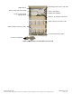
4.1 Enclosure Preparation
Remove the protective covering from the enclosure.
NOTE: Inspect the packing slip to verify that all equipment is there.
If batteries are on a separate pallet, they should not be installed until after the enclosure has been secured. If the
batteries are going to be placed within the enclosure, the inter-unit connectors must be installed.
Inspect moving parts, hardware, connectors, and installed equipment.
NOTE: In case of damage, report it according to procedure.
Remove and properly dispose of all packaging.
4.2 Lifting Preparation
ATTENTION:
All local safety practices and guidelines must be followed while lifting the enclosure.
Do not lift enclosure with batteries installed.
All personnel involved with lifting and placing the enclosure should wear head and eye protection
and gloves when required.