
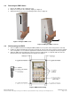
Owner's manual

Argus Technologies Ltd. 010-592-C0 Rev G WC
Printed in Canada. © 2008 Argus Technologies Ltd. ARGUS is a registered trademark of Argus Technologies Ltd. All Rights Reserved. Page 11 of 23
4.11 DC Output And Alarm Wiring
Recommended wire size:
• DC output: 2 x #16 AWG
• Alarm wiring: 5 x #24 AWG
• Ground: #16 AWG
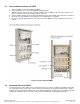
1. If wall-mounting the FMPS, select a knockout to the right of the DC output block and remove it using a
hammer and punch.
2. Insert the terminal end of the customer-supplied DC and alarm wiring through the sealing nut of the Heyco
fitting (provided), and through the selected knockout.
3. Connect the ground wire to #10 ground stud, M4 thread (optional ground reference wire to ONT).
4. Run the #16 AWG DC wiring and #24 AWG alarm wiring through the threaded end of the Heyco fitting and
mate the fitting halves. Tighten snug.
NOTE: Recommended hybrid wire for use is Belden P/N YR53034 or equivalent.
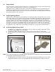
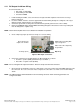
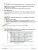
5. Create a drip loop (Figure 9) and use tie-wraps to secure the wiring.
FMPS output is floating with
respect to ground
Either side of the output may
be grounded
Drip loop
Pin for pin the two
outputs are common
Tie-wraps (2 PL)
Figure 9–DC output connections
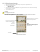
6. Connect the terminal end of the DC wiring to the DC output block as follows:
• Red wire = positive (RED) (48Vdc with respect to Black – )
• Black wire = negative return (BLACK)
NOTE: Do not over-tighten the output connections. Excessive torque can break the connectors.
7. Open (pull out) the alarm IDC connectors (small orange connectors) and insert the #24 AWG alarm wires into
the connectors. Press the connectors shut to complete the connections. See inside cover for alarm wiring
details.
NOTE: The FMPS complies with PacketCable™ alarm monitoring standards. Alarm monitoring parameters are
configured HI Active.