IDH3 Technical Manual DOCSIS® HMS Embedded Transponder Effective: January 2010 Alpha Technologies ®
Power Alpha Technologies 2 ® 745-420-B0-001 Rev.
IDH3 DOCSIS® HMS Embedded Transponder Installation and Technical Manual 745-420-B0-001, Rev. A Effective Date: January 2010 Copyright© 2010 Alpha Technologies, Inc. A Member of the Alpha Group Alpha denies responsibility for any damage or injury involving its enclosures, power supplies, generators, batteries or other hardware, manufactured by Alpha or members of the Alpha Group, when used for an unintended purpose, installed or operated in an unapproved manner, or improperly maintained.
Table of Contents Safety Notes .......................................................................................................................... 6 1.0 2.0 Introduction to the DOCSIS® Transponder ................................................................. 7 1.1 System Overview ............................................................................................. 8 1.2 LED Indicators ...............................................................................................
List of Figures Fig. 1-1, IDH3 Transponder with EDSM ................................................................................ 7 Fig. 1-2, System Interconnection Diagram 1 ......................................................................... 8 Fig. 1-3, System Interconnection Diagram 2 ......................................................................... 9 Fig. 2-1, Attaching the PCB Standoff ................................................................................... 14 Fig.
Safety Notes Review the drawings and illustrations contained in this manual before proceeding. If there are any questions regarding the safe installation or operation of the system, contact Alpha Technologies or the nearest Alpha representative. Save this document for future reference. To reduce the risk of injury or death and to ensure the continued safe operation of this product, the following symbols have been placed throughout this manual. Where these symbols appear, use extra care and attention.
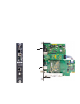
1.0 Introduction to the DOCSIS® Transponder The IDH3 Transponder for the XM2 power supply manages network powering through existing cable modem or high speed data infrastructure. A single transponder can monitor and manage multiple power supplies, multiple strings of batteries, and one generator. The transponder transmits data to a management system via the existing DOCSIS network. SNMP (Simple Network Management Protocol) keeps bandwidth use to a minimum.
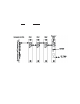
1.0 Introduction to the DOCSIS® Transponder, continued 1.1 System Overview The IDH3 Transponder obtains data from the EDSM (Enhanced Digital Status Monitoring) interface card through an XM2 Power Supply. The EDSM collects data directly from the battery strings or from the AlphaBus Communications Network, depending on system configuration.
1.0 Introduction to the DOCSIS® Transponder, continued 1.1 System Overview, continued Equipment monitored via the AlphaGuard™: The AlphaGuard performs electrical compensation for differences in individual batteries in the string. The unit can be configured to pass measurements from the battery string to a status monitoring device (EDSM card, DOCSIS transponder, etc.) via an interface cable.
1.0 Introduction to the DOCSIS® Transponder, continued 1.
2.0 Transponder Installation Steps to a Successful Installation: • Operator’s IT Department must allow the transponder’s Cable Modem (CM) to obtain an IP address from the DHCP Server. • Operator’s IT Department must provision the transponder, as described in the following section. • Operator’s network security policies must allow SNMP traffic to pass between transponder and SNMP manager. • Install the transponder and any related equipment in the power supply. • Connect an RF drop.
2.0 Transponder Installation, continued 2.1 Provisioning the Transponder, continued 2.1.2 Transponder Configuration Many SNMP Management Applications require an SNMP Trap to be sent from the transponder for self-discovery and for alarm notifications. An SNMP Trap destination address can be specified to the IDH3 through the DOCSIS configuration files docsDevNmAccessTable (RFC 2669). 12 745-420-B0-001 Rev.
2.0 Transponder Installation, continued 2.2 Verifying Firmware Version and Device Address Before removing the Inverter Module (IM), verify the power supply firmware version and device address are correct. • IM firmware v3.00.0 is the minimum version compatible with the DOCSIS Embedded Transponder. • The power supply device address must not be set to zero, and no two power supplies monitored by a single transponder may have the same address. 1.
2.0 Transponder Installation, continued 2.3 Installing the Transponder Hardware, continued 4. Attach the new transponder ribbon cable supplied to the 10-pin connector on the transponder. The connectors are keyed to prevent incorrect orientation. 5. Attach the plastic standoff to the transponder PC board as shown in Fig 2-1 6. Verify that the MAC address label is installed on the transponder. If the label is missing, locate the label in the packaging and apply to the transponder as shown in Fig 2-2. 7.
2.0 Transponder Installation, continued 2.4 RF Connection Connect the RF drop to the RF connector on the transponder. The drop must have a properly installed ground block in or on the power supply enclosure. Recommended forward RF level is 0 dBmV. RF Connection Ground Surge Protector (User Provided) RF Cable to Headend See Caution Below Fig. 2-3, RF Connection with Ground Block Alpha requires installing a grounded surge suppressor (Alpha P/N 162-028-10 or equivalent). 2.
3.0 Network/Element Management Software 3.1 Provisioning the SNMP Manager The following MIB (Management Information Base) files are required for the SNMP Manager to collect data from the transponders. These files can be found on the Society of Cable Telecommunications (SCTE) web site www.scte.org.
4.0 Using the Ethernet (Craft) Port 4.1 IDH3 Web Interface 4.1.1 Overview A web interface is available on the IDH3 transponder. The default port for HTTP traffic is port 80, but can be configured to use other ports via the Tollgrade httpMgmt MIB. HTTP port configuration is available for the cable modem interface (via the cable modem IP address) and the CPE interface (via the Local connection). The Local connection’s IP address is 192.168.100.
4.0 Using the Ethernet (Craft) Port, continued 4.1 IDH3 Web Interface, continued 4.1.1 System Overview, continued Depending on the network configuration of the computer you are using to connect to the IDH3 transponder, it may be necessary to set the network interface to a temporary static IP address. This will make itself known if you can’t bring up the first web page using 192.168.100.1.
4.0 Using the Ethernet (Craft) Port, continued 4.1 IDH3 Web Interface, continued 4.1.1 System Overview, continued You’ll see another dialog box, and enter the values as they appear in the diagram below: Click on “OK” and try to connect to the transponder once again using 192.168.100.1 in your Web browser. 745-420-B0-001 Rev.
4.0 Using the Ethernet (Craft) Port, continued 4.1 IDH3 Web Interface, continued 4.1.1 System Overview, continued NOTE: The IDH3 web pages do not automatically refresh, so the user must manually reload each one to view the most current data. Configuring the sysName and sysLocation OIDs It is also possible to configure the sysName (1.3.6.1.2.1.1.5.0) and sysLocation (1.3.6.1.2.1.1.6.0) OIDs from the web interface. This feature is password protected. There are both Admin and User usernames and passwords.
4.0 Using the Ethernet (Craft) Port, continued 4.1 IDH3 Web Interface, continued 4.1.2 Status Page for Firmware Information This homepage provides details on the firmware running in the cable modem and allows navigation to other diagnostic information via the links provided.. Fig. 4-1, Status Page for Firmware Information 745-420-B0-001 Rev.
4.0 Using the Ethernet (Craft) Port, continued 4.1 IDH3 Web Interface, continued 4.1.3 Status Page for Connection Information This page provides detailed status information related to the current connection to the CMTS. Fig. 4-2, Status Page for Connection Information 22 745-420-B0-001 Rev.
4.0 Using the Ethernet (Craft) Port, continued 4.1 IDH3 Web Interface, continued 4.1.4 Status Page for the SNMP Event Log This page provides recent event log entries. Fig. 4-3, Status Page for the SNMP Event Log 745-420-B0-001 Rev.
4.0 Using the Ethernet (Craft) Port, continued 4.1 IDH3 Web Interface, continued 4.1.5 HMS Power Supply Data Page This page displays HMS power supply, generator, and generic I/O data. The coloring of an individual parameter indicates its alarm level as follows: · Light grey: Parameter is not in alarm. · Yellow: Parameter is in minor alarm. · Red: Parameter is in major alarm. Fig. 4-4, HMS Power Supply Data Page 24 745-420-B0-001 Rev.
4.0 Using the Ethernet (Craft) Port, continued 4.1 IDH3 Web Interface, continued 4.1.6 Generator Data Page Click on the GEN8 link to see the Generator data page. Fig. 4-5, Generator Data Page 745-420-B0-001 Rev.
5.0 Specifications Power Supplies Supported: XM2-HP, XM2 DOCSIS Compatibility: DOCSIS 1.1, 2.0 Monitoring Protocol: SNMP v1 Devices Monitored: Power Supply, Batteries and Generator (compatible with ANSI/SCTE 25-3 2002, formerly HMS 022) Hardware RF Cable Interface: F-connector, female, 75Ohm Local Interface: Ethernet interface for direct web page access to diagnostic information.
6.
Power Alpha Technologies Alpha Technologies 3767 Alpha Way Bellingham, WA 98226 USA Tel: +1 360 647 2360 Fax: +1 360 671 4936 Web: www.alpha.com Alpha Technologies Ltd. 4084 McConnell Court Burnaby, BC, V5A 3N7 CANADA Tel: +1 604 430 1476 Fax: +1 604 430 8908 Alpha Technologies Europe Ltd.