Nickel Cadmium Clear Case Pocket Plate Battery Technical Manual Nickel Cadmium Clear Case Battery Effective: February 2007 Alpha Technologies
Power Alpha Technologies ®
Nickel Cadmium Clear Case NI-CD-CLEAR-CASE Effective Date: February 2007 Copyright© 2007 Alpha Technologies, Inc. member of The GroupTM NOTE: Photographs contained in this manual are for illustrative purposes only. These photographs may not match your installation. NOTE: Operator is cautioned to review the drawings and illustrations contained in this manual before proceeding.
Table of Contents Safety Notes........................................................................................................................... 6 1.0 Installation................................................................................................................... 8 2.0 Electrolyte.................................................................................................................... 9 3.0 4.0 2.1 Preparation..........................................................
Tables and Figures Table 3-1, Equalizing Charge Voltage.................................................................................. 12 Table 3-2, Floating Charge Voltage...................................................................................... 13 Table 4-1, Inspection Check Points...................................................................................... 13 Fig. 7-1, Charge Recording Form.........................................................................................
Safety Notes Review the drawings and illustrations contained in this manual before proceeding. If there are any questions regarding the safe installation or operation of the system, contact Alpha Technologies or the nearest Alpha representative. Save this document for future reference. To reduce the risk of injury or death, and to ensure the continued safe operation of this product, the following symbols have been placed throughout this manual. Where these symbols appear, use extra care and attention.
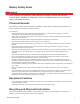
Battery Safety Notes WARNING! Nickel cadmium (NiCd) batteries contain dangerous voltages, currents and corrosive material. Battery installation, maintenance, service and replacement must be performed only by authorized personnel. Chemical Hazards The electrolyte in Nickel Cadmium batteries, consisting of a dilute caustic potash solution with a lithium hydroxide component, is harmful to the skin and eyes.
1.0 Installation Alpha’s Clear Case Nickel Cadmium battery is designed and manufactured to provide battery power to support various industrial backup power applications. This high performance battery has four different discharge models to specifically meet the demands of the powering application. • HDV Range (Very High) • HDH Range (High) • HDM Range (Medium) • HDS Range (Long) NiCd batteries do not emit any corrosive fumes and can be placed near sensitive electrical equipment.
2.0 Electrolyte WARNING! Electrolyte can cause serious inflammation of the skin and destroys clothing; always wear protective equipment. If contact with the skin or eyes occurs, obtain medical treatment as soon as possible. 2.1 Preparation The electrolyte used in nickel cadmium batteries is a solution of chemicaly pure potassium hydroxide (commonly known as caustic potash) mixed with powder lithium hydroxide and dissolved in distilled or ion-exchange purified water.
2.0 Electrolyte, continued 2.3 Topping Up Since water electrolysis and evaporation are constantly taking place in the cell, causing the electrolyte level to lower over time, occasional topping up of the electrolyte is needed. • Check the electrolyte level visually from the outside of the cell. • Keep the electrolyte between the minimum and maximum level marks. Only use distilled or ion-exchange purified water to top off the electrolyte. NOTE: Charging accelerates the loss of water from the cell.
3.0 Charging NOTE: The charge state of the battery cannot be judged by measuring the specific gravity of its electrolyte. NOTE: Refer to your particular charger’s manual for specific instructions regarding charger setup and operation. About Charging Temperatures An electrolyte temperature of 68°F (20°C)–77°F (25°C) is ideal for charging. The temperature of the electrolyte gradually rises as charging continues.
3.2 General Charge, continued Cell voltage gradually rises as the charging continues. To maintain the charging current at the specified rate, raise the rectifier’s output voltage using the manual output voltage regulator. Taking measurements before and after charging and during discharge helps to track changes and identify problems. Use forms like those in section 7.0 to record the results. Wait two hours after charging before taking final measurements, to allow the electrolyte to cool sufficiently.
3.0 Charging continued 3.4 Floating Charge When connected to a floating charge, the battery is kept in a fully charged state. Floating charge voltage is normally 1.40–1.50Vpc (see Table 3-2) and the ampere is about 1/40 of a 5 hour rate current (1/200 C). Adjust these values accordingly; too much gassing or water consumption means the charging voltage is too high, whereas a gradual drop of capacity indicates the charging voltage is too low.
5.0 Storage A charged battery can be stored for up to six months but will suffer a gradual loss in capacity. If a battery is to be put back into service in less than six months, fully recharge it every three months with the 10 hour rate current for 14 hours. If a battery will be stored for a period longer than six months, completely discharge it, completely remove the electrolyte, thouroughly dry the inside, and close the vent plug of each cell.
7.0 Forms Charging Recording Form Record before charging and two hours after Model of Battery Date Battery Bank No. Room Temperature Charging Current Total Battery Voltage Remarks Cell # Voltage S.G. of Electrolyte Electrolyte Temperature NOTE: Wait two hours before taking final readings, to allow the electrolyte to cool. Fig.
7.0 Forms. continued Discharge Recording Form Model of Battery Date Battery No. Room Temperature Charging Current Total Battery Voltage Remarks Cell # Inital Voltage Cell Voltage at Time Period End 15min 30min 1hr 2hr 3hr 4hr 4:30hr 5 hr Fig.
8.0 Specifications 8.1 General Specifications Specifications are subject to change without notice.
8.0 Specifications, continued 8.2 Discharge Voltage Specifications are subject to change without notice. Table 8-2, Discharge End Voltage 1.
8.2 Discharge Voltage, continued Specifications are subject to change without notice. Table 8-3, Discharge End Voltage 1.
8.2 Discharge Voltage, continued Specifications are subject to change without notice. Table 8-4, Discharge End Voltage 1.
8.2 Discharge Voltage, continued Specifications are subject to change without notice. Table 8-5, Discharge End Voltage 1.
8.2 Discharge Voltage, continued Specifications are subject to change without notice. Very High-Rate Type HDV-P Very High-Rate Type HDH-P Table 8-6, Discharge End Voltage 0.9Vpc Very High-Rate Type HDV-P Very High-Rate Type HDH-P Table 8-7, Discharge End Voltage 0.
Power Alpha Technologies ® Alpha Industrial Power, Inc 1075 Satellite Blvd. Suite 400 Suwanee, GA 30024 USA Tel: +1 678 475 3995 Fax: +1 678 584 9259 Alpha Technologies 3767 Alpha Way Bellingham, WA 98226 USA Tel: +1 360 647 2360 Fax: +1 360 671 4936 Web: www.alpha.com Alpha Technologies Ltd. 4084 McConnell Court Burnaby, BC, V5A 3N7 CANADA Tel: +1 604 430 1476 Fax: +1 604 430 8908 Alpha Technologies Europe Ltd.