PWE/PME Series Pole and Ground-mount Enclosures PWE/PME Series Technical Manual Effective: April 2009 Alpha Technologies ®
Power Alpha Technologies ®
PWE/PME Technical Manual 031-161-B0-006, Rev. F Effective Date: April 2009 Copyright© 2009 Alpha Technologies, Inc. member of The GroupTM NOTE: Photographs contained in this manual are for illustrative purposes only. These photographs may not match your installation. NOTE: Operator is cautioned to review the drawings and illustrations contained in this manual before proceeding.
List of Tables and Figures Safety Notes .......................................................................................................................... 6 1.0 2.0 3.0 4 Introduction ................................................................................................................. 9 1.1 PWE/PME Series Enclosures ........................................................................ 10 1.2 PWE Enclosure Diagram ..................................................................
List of Tables and Figures Fig. 1-1, PWE-6 Enclosure ................................................................................................................................. 9 Fig. 1-2, PWE/PME Series Enclosures ............................................................................................................ 10 Fig. 1-3, PWE-3 Enclosure (configurations may vary).......................................................................................11 Fig. 1-4, Battery Integration Tray ...
Safety Notes Review the drawings and illustrations contained in this manual before proceeding. If there are any questions regarding the safe installation or operation of this product, contact Alpha Technologies or the nearest Alpha representative. Save this document for future reference. To reduce the risk of injury or death, and to ensure the continued safe operation of this product, the following symbols have been placed throughout this manual. Where these symbols appear, use extra care and attention.
Battery Maintenance Guidelines The battery maintenance instructions listed below are for reference only. Battery manufacturer’s instructions for transportation, installation, storage or maintenance take precedence over these instructions. • • • • • • • • To prevent damage, inspect batteries every 3 months for: Signs of battery cracking, leaking or swelling. The battery should be replaced immediately by authorized personnel using a battery of the identical type and rating. Signs of battery cable damage.
Battery Safety Notes WARNING! Lead-acid batteries contain dangerous voltages, currents and corrosive material. Battery installation, maintenance, service and replacement must be performed only by authorized personnel. Chemical Hazards Any gelled or liquid emissions from a valve-regulated lead-acid (VRLA) battery contain dilute sulfuric acid, which is harmful to the skin and eyes. Emissions are electrolytic, and are electrically conductive and corrosive.
1.0 Introduction PWE/PME Series enclosures support distributed powering architectures in pole and ground-mount broadband applications. Ideal for use in all climates, each enclosure comes with a removable lockable door and easy opening lid. Standard features include a high-magnetic circuit breaker, duplex AC receptacle, and service power inserter.
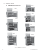
1.0 Introduction, continued 1.1 PWE/PME Series Enclosures PWE-4 PWE-3 PWE-8 PWE-6 PME PWE-9 PWE-D36 Fig. 1-2, PWE/PME Series Enclosures 10 031-161-B0-006, Rev.
1.0 Introduction, continued 1.
1.0 Introduction, continued 1.3 Optional Features Feature Description AC Indicator (ACI) The ACI verifies voltage output with a green light. Located next to the LRI lamp on the outside of PWE/PME Series enclosures, it is easily monitored from the ground. Because of its longer life, Alpha recommends the ACILL (long life) LED over the incandescent light bulb design. 60V and 90V models are available. Battery Heater Mat (BHM) The BHM is AC line operated and turns on at 40°F.
1.0 Introduction, continued 1.4 The Battery Integration Tray The optional Battery Integration Tray (BIT) eliminates the need for battery slide trays, and allows batteries to be individually installed or removed in PWE-3/6 enclosures. Each battery is connected directly to the BIT using modular 50A connectors. The BIT further improves wire management by pre-terminating connections for status monitoring voltage sense leads and for the AlphaGuard battery balancer.
1.0 Introduction, continued 1.5 PWE Battery Tray Latch Operation (optional) As an added safety precaution, the PWE series features a latch to hold the optional battery slide trays securely in place, in both open and closed positions. The latch automatically locks in place when the tray is pushed back in. CAUTION! The maxiumum weight of the battery slide tray is indicated by the color of the cap on the latch: Black: max. 72lbs (32.7kg) (legacy enclosures); red: max. 82lbs (37.
1.0 Introduction, continued 1.6 PWE Lid Removal 2. Pull Up 1. Pull Out The lid can be completely removed by disconnecting retention strap Fig, 1-6, PWE Lid Removal 1.7 PWE/PME Enclosure Specifications Model Dimensions (W x H x D) (in/mm) Shipping Weight (lb/kg) Battery Capacity Approx. Full System Weight (lb/kg) PWE-3 24.25 x 24.5 x 14/ 616 x 622 x 356 38/17.2 3 349/158.3 PWE-4 30.25 x 24.75 x 16/ 768 x 629 x 406 59/26.8 4 445/201.8 PWE-6 24.25 x 36.75 x 14 616 x 933 x 356 56/25.
2.0 Installation CAUTION! • • • • Never transport the unit with installed batteries. Doing so can cause injury or damage to the enclosure and installed equipment. Install the batteries after you transport the unit to the site and secure it to the pole. Alpha recommends that you position the enclosure on the opposite side of the pole from traffic. This reduces the danger of falling equipment in the event that a pole is struck by an automobile. Mounting bolts must completely penetrate the wooden pole.
2.0 Installation, continued 2.1 Pole-mounting, continued 2.1.1 Wooden Pole, continued 5. Secure the brackets to the pole using the 5/8" (15.9mm) machine bolts, washers, and nuts. 6. Lift the enclosure onto the brackets. It might be necessary to rock and pull the enclosure to properly seat it on the brackets. 7. Secure the enclosure to the brackets using the 3/8" x 3/4" (9.5mm x 19mm) hex bolts. 8. Make sure all nuts and bolts are fully tightened and the flanges of the brackets seat in the wood. 9.
2.0 Installation, continued 2.1 Pole-mounting, continued 2.1.2 Concrete or Steel Pole Tools and Materials Required (customer supplied): • Stainless steel banding (or equivalent), rated to support loaded enclosure and sized for pole diameter • Assorted sockets Procedure: 1. Unpack the enclosure and galvanized brackets; turn the enclosure facedown on a soft surface. 2. Slide a bracket up through the enclosure’s lower mounting bracket. The bracket’s flanges must face away from the enclosure.
2.0 Installation, continued 2.1 Pole-mounting, continued 2.1.2 Concrete or Steel Poles, continued 18" (457.2mm) 18" 18" (457.2mm) 18" Fig. 2-2, PWE/PME Series Steel or Concrete Pole-mounting 031-161-B0-006, Rev.
2.0 Installation, continued 2.1 Pole-mounting, continued 2.1.3 Enclosure Grounding: Pole-mount NOTE: Alpha recommends using the grounding method illustrated below. The grounding method may vary depending on local codes and other site-specific characteristics. External Grounding Lug #6 Bare Copper Wire Power Meter 1/2" (12.7mm) X 8' (2.4m) Copper Ground Rod Ground Wire Fig. 2-3, Enclosure Grounding for Pole-mount Configuration (with generator backup) 20 031-161-B0-006, Rev.
2.0 Installation, continued 2.2 Ground-mount Installation: PWE-4, PWE-8, PWE-9, PWE-D36 CAUTION! Never transport the unit with installed batteries. Doing so can cause injury to the installer, or damage the enclosure and equipment. Install the batteries after you transport the unit to the site and secure it to the pad. ATTENTION: It is the responsibility of the installer to meet the requirements of all applicable national and local codes.
2.0 Installation, continued 2.2 Ground-mount Installation: PWE-4, PWE-6, PWE-8, PWE-9, PWE-D36, continued 2.2.1 Pre-Installation, continued Alpha Technologies, Inc. cannot anticipate all the ways a vehicle could threaten an installed system or the specific type of protection that is appropriate for a particular location. The following installation drawing for Alpha’s Standby Power systems are general recommendations and not intended to be a specific guideline for protecting the equipment.
2.0 Installation, continued 2.2 Ground-mount Installation: PWE-4, PWE-8, PWE-9, PWE-D36, continued 2.2.2 Enclosure Grounding: Ground-mount NOTE: • • • Alpha generally recommends using the grounding method illustrated below. However, the grounding method appropriate for a particular site depends on local codes, the NEC (National Electric Code), and other site-specific characteristics.
2.0 Installation, continued 2.2 Ground-mount Installation PWE-4, PWE-8, PWE-9, PWE-D36, continued 2.2.3 Ground-mount Installation, PWE-3, PWE-9 and PWE-D36 NOTE: PWE-9 and PWE-D36 enclosures require a pedestal mount kit and Coax Raceway for ground installation. Pedestal kit part number: 745-400-20 (gray); 745-400-21 (white). Coax Raceway part number: 604-432-B1 (gray); 604-432-C3 (white). Tools and Materials Required (customer supplied): • Four 1/2" (12.
2.0 Installation, continued 2.2 Ground-mounting PWE-4, PWE-8, PWE-9, PWE-D36, continued 2.2.3 Pad PWE-9 and PWE-D36 Ground-mount Installation, continued Outside of Pedestal Inner Flange on Bottom of Pedestal Enclosure Mounting Holes Coax Raceway Mounting Pedestal Anchor Holes Coax Raceway Coax Sweep 21.38" (543mm) (on center) 3.25" (82.6mm) Pedestal Anchor Holes 3" (76.2mm) 9" (228.6mm) (on center) Utility Sweep 3.8" (96.5mm) Fig.
2.0 Installation, continued 2.2 Ground-mount Installation, PWE-4, PWE-8, PWE-9, PWE-D36, continued 2.2.4 PWE-4 and PWE-8 Ground-mount Installation NOTE: PWE-4 and PWE-8 enclosures require a ground mount kit for ground installation. Alpha P/N 745-067-20. This kit only fits enclosures manufactured after April 2002. See Fig. 2-11 to identify compatible enclosures. Tools and Materials Required (customer supplied): • Four 1/2" (12.7mm) anchor bolts (Hilti style recommended) • Four 1/2" (12.
2.0 Installation, continued 2.2 Ground-mount Installation, PWE-4, PWE-8, PWE-9, PWE-D36, continued 2.2.4 PWE-4 and PWE-8 Ground-mount Installation, continued Anchor Bolt Locations Fig. 2-9, Ground-mounting Brackets, Installed 27" (685.8mm) 11" (279.4mm) Front of Enclosure Fig. 2-10, Enclosure Ground-mount Footprint NOTE: This kit is only compatible with enclosures manufactured after April 2002.
2.0 Installation, continued 2.3 Connecting Utility Power WARNING! ONLY qualified personal should connect the utility power. Power must be connected in compliance with local electrical codes, and common safety practices must be observed. ATTENTION: • Connection to utility power must be approved by the local utility before installing the power supply.
2.0 Installation, continued 2.3 Connecting Utility Power, continued In most cases, the following configurations qualify for service entrance use. However, conflicting codes may apply. Always contact your local utility to verify that the wiring conforms to applicable codes. 240Vac Service (XM2-915 240 Power Supply; XM Series 2 922-48 for PWE-4 and PWE-8) 120Vac 20A Service (XM2-915 120 Power Supply) 120Vac 15A Service (XM2-615 120 Power Supply) 031-161-B0-006, Rev.
2.0 Installation, continued 2.3 Connecting Utility Power, continued To Utility To Utility L2 (Red) L1 (Black) Copper Ground Wire #8 AWG min. Neutral (White) Neutral (White) Copper Ground Wire #8 AWG min. Breaker Breaker Neutral Bus Grounding Point Made to Enclosure Wall L1 (Black) Neutral Bus Grounding Point Made to Enclosure Wall L1 (Black) 120Vac L1 To Enclosure Receptacle L2 240Vac To Enclosure Receptacle Fig.
2.0 Installation, continued 2.3 Connecting Utility Power, continued Ground Line 2 Line 1 ON OFF ISE 240V 15A Neutral Ground Line ON ISE 120V 20 A OFF Neutral Ground Line ON ISE 120V 15A OFF Fig. 2-14, Typical ISE (Internal Service Entrance) Receptacle Wiring 031-161-B0-006, Rev.
2.0 Installation, continued 2.3 Connecting the Utility Power, continued Neutral Ground Line Ground Line 2 Line 1 ON ON OFF OFF BQO 240V, 15A Neutral Ground Line 2 Line 1 BQO 120V, 20A Neutral Ground Line ON OFF BQO 240V, 120V ON ON OFF OFF BQO 120V, 20A Dual Receptacle, Dual Breaker Fig. 2-15, Typical BQO (Breaker Quad Option) Receptacle Wiring 32 031-161-B0-006, Rev.
2.0 Installation, continued 2.3 Connecting the Utility Power, continued Cable Output Service Drop External Grounding Lug Utility Power Input Meter 5.5' 5' 6" (1.7m) Service Entrance Fig. 2-16, PWE Pole-mount Configuration NOTE: Alpha offers a Meter Convenience Assembly (MCA) as a cost-effective alternative to building an assembly on-site. The MCA is a factory-configured, pole-mount meter and service disconnect with integral bracket that makes installation simple and consistent. 031-161-B0-006, Rev.
2.0 Installation, continued 2.3 Connecting Utility Power, continued Meter Socket Clamp Ground Line 1 Line 2 Neutral Fig. 2-17, Meter Wiring Line 1 Ground Bus Line 2 Neutral O N 20 O FF Neutral Bus Line 1 Line 2 Neutral Circuit Breaker (Square D Q0220) ON 20 OFF Circuit Breaker (Square D Q0220) Line 2 Ground Neutral Bus Line 2 Ground Neutral Neutral Ground Line 1 Ground Clamp #8 AWG (Min.) Copper Ground Wire Fig.
2.0 Installation, continued 2.4 Connecting the Coaxial Cable 2.4.1 Coaxial Cable Surge Protector Installation Instructions Alpha recommends using coaxial surge suppression for enclosure protection. The Coax Surge Protector with Ground Block (Alpha P/N 745-910-21) includes 75 ohm surge suppressor, mounting hardware, and waterproofing grommet. Required Tools: • Drill with 3/16" (4.8mm) bit. For older enclosures a 3/4" (19mm) bit is also needed. • Phillips screwdriver • 3/8" (9.
2.0 Installation, continued 2.4 Connecting the Coaxial Cable, continued 2.4.2 Connecting the Service Power Inserter (SPI) WARNING! Disconnect all power sources from the SPI (Service Power Inserter) before removing its cover. Verify that the SPI is disconnected from both the utility power and the power supply before beginning procedure. PWE Enclosures PME Enclosures Power Suppy Output (Coaxial Cable) SPI SPI Power Suppy Output (Coaxial Cable) Fig. 2-20, SPI Locations Procedure: 1.
2.0 Installation, continued 2.5 Battery Installation 2.5.1 Battery Date Code Usage and Identification Every battery contains a DATE CODE. This code is usually located near the positive (+) terminal, and must be recorded in the maintenance log. If you use batteries other than those installed by Alpha, consult the batteries’ manufacturer’s documentation for date code type and placement. NOTE: The date code scheme and location varies depending on the age of the battery used. Month: June Year: 2005 Fig.
2.0 Installation, continued 2.5 Battery Installation, continued 2.5.2 Battery Installation Procedure WARNING! To prevent arcing, never allow live battery cables to make contact with the enclosure. Disconnect battery leads, or wrap the cable lugs with electrical tape. CAUTION! Threaded insert terminals require the use of 3/4" (19mm) bolts. The use of 1" (25.4mm) bolts will seriously damage the battery. The only exception is the terminal with the large spacer for the in-line fuse link. See section 2.5.
2.0 Installation, continued 2.5 Battery Installation, continued 2.5.3 Connecting the Battery Integration Tray (PWE 3/6 Only) 1. Connect the battery cable kits (Alpha P/N 875-690-20) to each battery, and to matching connector on the Battery Integration Tray (BIT). Torque to the battery manufacturer's specification (for AlphaCell batteries see battery label). 2. If applicable, secure the batteries with the optional Battery Retaining Bar (BRB) (Alpha P/N 744-346-20).
2.0 Installation, continued 2.5 Battery Installation, continued 2.5.4 Battery Terminal Connections NOTE: • Various types of batteries with different mounting styles and hardware may be shipped with the system. ALWAYS refer to the battery manufacturer’s specifications for correct mounting hardware and torque requirements. Use only the hardware and torque recommended by the battery manufacturer.
2.0 Installation, continued 2.5 Battery Installation, continued 2.5.4 Battery Terminal Connections, continued Flag Terminals Battery Sense Cable Flat Washer Flat Washer Split Washer Nut 1" x 1/4-20 Bolt Battery Cable Battery Terminal Nut Split Washer Flat Washer 1" (25.4mm) x 1/4-20 Bolt Split Washer Battery Cable Flat Washer In-Line Fuse Link Flat Washer 1" (25.4mm) or 3/4" (4.8mm) x 1/4-20 Bolt Spacer Battery Terminal Fig. 2-26, Flag Battery Terminal Connections 031-161-B0-006, Rev.
2.0 Installation, continued 2.5 Battery Installation, continued 2.5.5 Battery Wiring Diagrams Temperature Probe (Connected to XM2) B L A C K (-) R E D (+) Battery Cable Connector (to XM2 Power Supply) Black (-) Red (+) 3 2 1 RTS (Taped to side of battery) In-line Fuse (optional) Fig.
2.0 Installation, continued 2.5 Battery Installation, continued 2.5.5 Battery Wiring Diagrams, continued CAUTION! If using the optional slide tray, zip-tie the negative black wire to the center battery interconnection cable. This will prevent the wire interfering with slide tray closure.
2.0 Installation, continued 2.5 Battery Installation, continued 2.5.5 Battery Wiring Diagrams, continued R E D (+) B L A C K (-) R E D (+) B L A C K (-) Battery Cable Connectors (to XM2 Power Supplies) Black (-) Red (+) Red (+) 3A 2A 1A Upper Tray RTS (Taped to side of battery) Temperature Probe (Connected to XM2) In-line Fuse (optional) Black (-) 3B 2B 1B RTS (Taped to side of battery) Lower Tray In-line Fuse (optional) Fig.
2.0 Installation, continued 2.5 Battery Installation, continued 2.5.5 Battery Wiring Diagrams, continued R E D (+) B L A C K (-) Battery Cable Connector (to XM2 Power Supply) Temperature Probe (Connected to XM2) RTS (Taped to side of battery) Red (+) Black (-) 3A 1A 4A 2A 3B 1B 4B 2B Upper Tray In-line Fuse (optional) Lower Tray In-line Fuse (optional) Fig. 2-31, PWE-8 Battery Wiring Diagram 031-161-B0-006, Rev.
2.0 Installation, continued 2.5 Battery Installation, continued 2.5.5 Battery Wiring Diagrams, continued R E D (+) Red (+) B L A C K (-) Battery Cable Connector (to XM2 Power Supply) Temperature Probe (Connected to XM2) In-line Fuse (optional) Black (-) 3A 2A 1A RTS (Taped to side of battery) Upper Tray In-line Fuse (optional) 3B 2B 1B Middle Tray In-line Fuse (optional) 3C 2C 1C Lower Tray In-line Fuse (optional) Fig. 2-32, PWE-9 Battery Wiring Diagram 46 031-161-B0-006, Rev.
2.0 Installation, continued 2.6 Installing the XM Series 2 Power Supply Installation Procedure: 1. Before installation, inspect the power supply for damage or loose connectors. 2. Place the XM Series 2 Power Supply in the lower-right compartment of PME enclosures, or the upper-right compartment of PWE enclosures. 3. Switch the BATTERY BREAKER on the front of the power supply OFF. This prevents the inverter from starting when the batteries are first connected to the power supply. See Fig. 2-32.
2.0 Installation, continued 2.7 Cooling Fan Installation NOTE: • This procedure requires a service power supply (for example, an APP 9015S or APP 9022S) to maintain power to the cable plant while fan is being installed. The fan kit for PWE-3, 4, 6, and 8 enclosures includes a fan assembly with a single fan. The PWE-9 and PWE-D36 enclosures’ kit includes a double fan assembly. The installation and wiring procedures, however, are identical.
2.0 Installation, continued 2.8 PWE-8 Solar Shield Installation Tools Required: • Drill • 3/16" (4.8mm) or #12 drill bit • Phillips screwdriver CAUTION! Drill only in the five locations indicated below. Center punches marked with a “ are reserved for the storm hood kit. ” (6 places) below Drill Here. 1 Installation Procedure: 1. Drill 3/16" (4.8mm) through-holes in the door at the locations shown (5 places). 2. Install the solar shield to the door, using the screws provided: #8-32 x 3/8" (9.
2.0 Installation, continued 2.9 Status Monitoring Transponder Bracket Installation Instructions Tools and Materials Required: • #10-32 nuts and flat washers • 3/8" (9.5mm) socket wrench or nut driver Installation Procedure: 1. Position status monitoring bracket over status monitor, and align bracket slots with PEM studs (located on enclosure). Status Monitoring Transponder Status Monitoring Bracket Bracket Slots 2.
3.0 Pole-mount Enclosure Maintenance Preventive Maintenance should be performed every three to six months. Inspect the Pole-mount Enclosure Perform a complete inspection of the Pole-mount Enclosure. Look for signs of rust and corrosion, paying particular attention to the battery trays. Clean any rust or corrosion immediately. Inspect the Mounting Brackets and Hardware Carefully inspect the mounting bracket and mounting hardware. Look for signs of unusual wear and loose hardware.
Power Alpha Technologies ® Alpha Technologies 3767 Alpha Way Bellingham, WA 98226 USA Tel: +1 360 647 2360 Fax: +1 360 671 4936 Web: www.alpha.com Alpha Technologies Ltd. 4084 McConnell Court Burnaby, BC, V5A 3N7 CANADA Tel: +1 604 430 1476 Fax: +1 604 430 8908 Alpha Technologies Europe Ltd.