
Manual

Power
®
Tools and Materials Required
• Hand drill
Center punch
Pop rivet tool with 5/32" nose piece
4-foot level
• #20 drill bit
• Tape measure
Masking tape
Pencil
Utility knife
Vacuum to remove metal shavings from cabinet interior
Lock, see Fig. 1 for dimensions
•
•
•
•
•
•
•
•
Material List, Security Bar Kit
UPE-3, UPE-6, UPE-M3, UPE-M6, PN and CE Series
Alpha P/N Description Qty
605-348-J2-002 Side Bracket 4
605-346-J2-003 Lock Bracket 2
605-345-R2-001 Security Bar 2
636-005-12 Rivets 12
633-294-12 Washers 12
Security Bar Field Installation InstructionsFiel
For UPE-3, UPE-6, UPE-M3, UPE-M6, PN Series and CE Series Enclosures
Each security bar kit contains the parts and accessories needed to secure one enclosure door. Enclosures with both a front and back
door, require two kits. Detailed placement specifi cations for each supported enclosure are in the Security Bar Field Installation Manual
(Search for P/N 745-847-C1-001) available at www.alpha.com.
Installation
The installation outlined below applies to each of the
supported enclosures. On all enclosures you must install
side brackets and lock brackets. The side brackets hold the
security bar, and the lock brackets hold the security lock.
See Figs. 4 and 5.
If needed, detailed placement specifi cations for each
supported enclosure are in the Security Bar Field
Installation Manual (Alpha P/N 745-847-C1-001) available
at www.alpha.com.
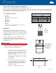
B
A
C
Where:
A= 5/16"
B= 3/4"
C= 2 1/2"
Fig. 1
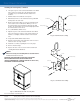
Using a 4-ft level and a pencil, mark the front of
the enclosure where you want to place the top side
brackets and bar. See recommended placement
specifi cations available at www.alpha.com (P/N 745-
847-C1-001). See Fig. 2.
Measure from the sides and mark the holes with a
center punch. These will be the top holes used by
the side brackets.
Remove the door.
Place cardboard behind the door jam to protect
the electronic equipment from the metal shavings
created during drilling. The carboard defl ects
the shavings, and should be removed when the
installation is complete.
Drill the holes using a #20 drill bit. See Fig 3.
1.
2.
3.
4.
5.
Fig. 2
Mark guide lines
to aid in placing
the top side
brackets and
security bar.
Guide Line
Drill holes
Fig. 3
A gas line runs behind the door jam on the 5K generator.
Turn off the gas prior to installing the security bar. Be
careful not to puncture or damage the line.
WARNING!
Page 1 of 2