Te43 Outdoor Auxiliary Enclosure Installation & Operation Manual
This page is intentionally left blank. Alpha Technologies Ltd. Printed in Canada. © 2010 Alpha Technologies Ltd. ALPHA and CORDEX are trademarks of Alpha Technologies Ltd. All Rights Reserved.
Te43 Outdoor Auxiliary Enclosure 057-104-20-101 The following documents and drawings are included in this manual to provide the necessary information required for routine operation and fault diagnosis o the system: Specifications: 029-030-B2 CSA/NRTL Equivalence 048-554-10 Safety and Installation Instructions 057-104-C0 Schematic 747-612-05 Outline drawings 057-104-06 Cust Connect, Intfc Kit, Te41 to Te40 w Cabl 747-602-08 Cust Connect, Intfc Kit, Te40 to Te40 w Cabl 747-603-08 Cust Connect,
Important Safety Instructions Save These Instructions This section contains important instructions that must be followed during the installation and maintenance of the equipment and batteries. Read all of the instructions before installing or operating the equipment, and save this manual for future reference. All electrical connections must be performed by licensed electricians only.
Electrical safety WARNING: Hazardous voltages are present at the input of power systems. The DC output from rectifiers and batteries, though not dangerous in voltage, has a high short-circuit current capacity that may cause severe burns and electrical arcing. Before working with any live battery or power system, follow these precautions: Remove all metallic jewelry, such as watches, rings, metal rimmed glasses, or necklaces. Wear safety glasses with side shields at all times during the installation.
Table of contents 1 Introduction ............................................................................................................................ 4 1.1 Scope of manual ........................................................................................................................ 4 1.2 Product overview........................................................................................................................ 4 1.3 Recommended pre-installation training ..................
4.4 Enclosure installation ................................................................................................................. 18 4.4.1 Enclosure preparation ....................................................................................................... 18 4.4.2 Lifting preparation ............................................................................................................. 18 4.4.3 Mounting the enclosure ................................................................
List of figures Figure 1 – Tempest Te43 Outdoor Battery Enclosure............................................................................... 4 Figure 2 – Miscellaneous compartment features ...................................................................................... 5 Figure 3 – Alarm block ............................................................................................................................. 6 Figure 4 – Miscellaneous enclosure features ...................................
1 Introduction 1.1 Scope of manual 1.2 This instruction manual covers features, installation, startup, and maintenance of the Alpha Technologies’ Tempest Te43 Outdoor Auxiliary Enclosure. Enclosure specifications are found in Alpha document #029-030-B2. Operation instructions for the system controller and related modules are provided in separate component manuals. Separate manuals are provided for batteries and other accessory equipment, such as HVAC.
2 Features 2.1 Equipment compartment The air-conditioned auxiliary enclosure is equipped with alarm wiring, an AC load termination for the air conditioner, a GFCI outlet, and a master ground bar. 2.2 Equipment mounting rails Four rails are installed in the enclosure. The rails are adjustable to a width of 19" or 23" (standard) and are also adjustable front-to-back.
Alarm block Figure 3 – Alarm block Alpha Technologies Ltd. Burnaby, British Columbia. Telephone: 604 436 5900 Fax: 604 436 1233.
2.3 Heating, ventilating, and air conditioning (HVAC) An air conditioner/heater package is mounted on the front door of the enclosure. It provides cooling/heating for the batteries and customer equipment. Refer to the HVAC manual supplied with the unit for operation and maintenance details. HVAC exhaust HVAC controls HVAC intake Three-point door latch Figure 4 – Miscellaneous enclosure features Alpha Technologies Ltd. Burnaby, British Columbia. Telephone: 604 436 5900 Fax: 604 436 1233.
2.4 Security The front door can be padlocked: Once closed, the front door handle can be secured with a padlock Figure 5 – Front door handle security Top cover intrusion alarm switch Rear panel intrusion alarm switch One per panel Switches can be offset-mounted Figure 6 – Top cover and rear panel intrusion alarm switch Alpha Technologies Ltd. Burnaby, British Columbia. Telephone: 604 436 5900 Fax: 604 436 1233.
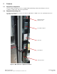
2.5 Rear access panel There are four removable rear access panels, one top 8” panel and three 24” panels below. The 24” panel directly below the 8” top panel is a slam latch panel. The top 8” panel and the lower two 24” panels use internal wingstuds that must be removed to lift off the panels. Pull on strap to release top 24”rear panel, then lift the panel up and out of the enclosure. Figure 7 – 24” top panel Remove each set of wing nuts, one on each side, to release the other panels.
2.6 Removable solar shield and hatch plate Remove eyebolts Remove solar shield exposing hatch plate To release hatch plate, pull the latch ring toward the rear of the enclosure in the direction shown by the large arrow To re-install, ensure the slam latch on the hatch plate is fully engaged. Re-install the solar shield by re-installing the eyebolts. Alpha Technologies Ltd. Burnaby, British Columbia. Telephone: 604 436 5900 Fax: 604 436 1233.
3 Transportation and storage 3.1 Packaging The enclosure and components are shrink wrapped and shipped on individual pallets. The enclosures and components must not be stacked on top of each other. The pallet is approximately 0.15 m H x 1.22 m W x 1.22 m D (6" H x 48" W x 48" D). The overall height including the pallet and enclosure is approximately 2.3 m (91"). Batteries are shipped on a separate pallet and packaged according to the manufacturer’s guidelines.
4 Installation 4.1 Pre-installation considerations The information in this section is intended to be used as a guideline only. There may be site-specific requirements and other factors that may require different procedures. For example, your jurisdictional codes and construction covenants may require different procedures than those in this manual. 4.1.1 Site selection The Te43 has been designed as an outdoor power system enclosure. The most common mounting structures are: An at-grade concrete slab.
4.1.3 Base layout dimensions Figure 9 – Base layout drawing and mounting hole location for Te43 Alpha Technologies Ltd. Burnaby, British Columbia. Telephone: 604 436 5900 Fax: 604 436 1233.
4.1.4 Concrete slab Cast-in-place or pre-cast concrete slabs can be used. Place the enclosure on the concrete slab. Use the enclosed Hilti HSL heavy-duty expansion anchor bolts or approved equivalents to secure the enclosure. Follow the specific recommendations from the fastener manufacturer to ensure that the securing device achieves its full structural capacity. Take into account the embedment depth and clear edge distances. Refer to the following figure.
4.1.5 Steel platform Use 1.27 cm (½”) diameter A325 structural bolts in conjunction with a backing plate/clasp to grip the underside of the grating. Once the enclosure is in place, secure the bolts on the inside using appropriate washers and bolts. See the following figure: Figure 11 – Installation on steel platform CAUTION: Installation on a wood base is not recommended. The compressive strength of the base material would not be able to maintain the load during a Type 4 seismic event.
4.2 Installation component requirements Concrete and metal grating mounting hardware is not supplied with the enclosure. AC electrical conduit, cable and fittings are not supplied with the enclosure. External DC conduit, cable and fittings are not supplied with the enclosure.
4.3 Installation tools and equipment 4.3.1 Tools Required Insulated tools are essential for DC power system installation.
4.4 Enclosure installation 4.4.1 Enclosure preparation Remove the protective covering from the system. The doors are designed to be locked with a pad-lock and are secured with tie-wraps for shipping. Cut the tie-wraps and open the doors. The inside of the enclosure contains the installation hardware. Inspect the packing slip to verify that you have received all the equipment that you ordered. 4.4.2 All documentation is packed inside the equipment compartment.
4.4.3 Mounting the enclosure Concrete slab Use the tagline to guide the enclosure as it is lifted. As the enclosure is lowered, align the mounting bolts and drop the enclosure into place. CAUTION: Follow all local safety practices and guidelines while lifting the enclosure. As the enclosure is lowered, ensure that it remains as level as possible and lines up with the anchoring bolt locations. Ensure the rubber mat is in the proper position.
4.4.5 Enclosure-to-enclosure interface The cable bridge kit between the enclosures can be mounted either on the left or right side of the enclosures. This kit must be installed before installing adjacent enclosure. See the enclosed drawings for the interface kit assembly. Remove the knockouts on the lower rear side panels. Apply a gasket around the opening used for cable routing.
4.4.6 Top hat installation A top hat is an optional structure. See enclosed drawings for the top hat kit assembly. Install the top hat kit before installing adjacent enclosures. Remove solar shield and mounting hardware including standoffs Install top hat and fasten with eyebolts Install standoffs on top edge of top hat Prepare and install the hatch panel Add Roxtec cable entry boots or conduits If aligned with other top hats, install feed through fittings Bolt the solar shield onto the enclosure 4.
4.5 Grounding DANGER: An enclosure that is not properly grounded presents an electrical hazard. A proper grounding system that meets or exceeds the specifications of the equipment must be designed and installed prior to or in conjunction with the construction of the mounting pad. The ground system must be bonded to the enclosure to ensure a “common” or “single-point” ground. Examples of grounds: New builds – a buried ground ring with a bare, solid conductor going to ground rods.
4.6 Air conditioner connections Only a licensed electrician should connect the AC input power to the enclosure Figure 17 – Battery enclosure air conditioner connections Alpha Technologies Ltd. Burnaby, British Columbia. Telephone: 604 436 5900 Fax: 604 436 1233.
5 Test and commissioning 5.1.1 Environmental/intrusion Check the operation of all enclosure features, such as the air conditioning unit settings, the high/low temperature alarms and the intrusion alarm. 5.2 Final cleanup Vacuum clean all metal filings and other debris from inside and around the enclosure. Ensure that: All cables and conduit are neatly secured. Access panels are installed correctly. All connections are tight. All breakers are on and the system is running without any alarms.
6 Maintenance The equipment requires regular maintenance. The maintenance should be done by qualified service personnel only. WARNING: HIGH VOLTAGE AND SHOCK HAZARD. Use extreme care when working inside the enclosure/shelf while the system is energized. Do not make contact with live components or parts. Static electricity may damage circuit boards, including RAM chips. Always wear a grounded wrist strap when handling or installing circuit boards. 6.
7 HVAC default settings Refer to the air conditioner manual for operation and maintenance details. 7.1 7.2 Air Conditioner/heater Description Setting Cooling system ON temperature Heating system ON temperature HVAC fail alarm (dirty filter, broken condenser, etc.) 80F (26.6C) 60F (15.5C) 300 psi, reset at 225 psi Temperature alarms Compartment thermostat Setting High temperature alarm (blue) 45C (113F) Low temperature alarm (red) -15C (5F) Alpha Technologies Ltd.
8 Alpha conventions 8.1 Numbering system Alpha Technologies uses an eight-digit drawing number system, which is broken into three blocks. The first three digits describe the category of the product; e.g., rectifier or fuse panel. The next three digits indicate the sequence in which the product number was allocated in a particular category.
Specifications for Alpha Te43 Auxiliary Enclosure Electrical Input Voltage: 120Vac, 60Hz single phase (for air conditioner and CFGI receptacle) Feeder Breaker: 15A recommended Mechanical Dimensions: 2134mm H x 762mm W x 762mm D (84" H x 30" W x 30" D) Weight: 205 kg (450 lb.
1 2 3 4 5 6 REVISION LTR DESCRIPTION DATE APPD AIR CONDITIONER AND GFCI WIRING: A A 4000 BTU/Hr AIR CONDITIONER BLU - #18 AWG 8 RED - #18 AWG 9 YEL - #18 AWG 10 N.C. TO TB9 COM TO TB10 N.O. TO TB11 TO ALARM WIRING TERMINAL BLOCKS (REFER TO SHEET 2) RETURN AIR N.C. EXT. OUTPUT LEAD (STATUS ALARM) COM N.O.
1 2 3 4 5 6 REVISION LTR DESCRIPTION DATE APPD ENCLOSURE TEMPERATURE & INTRUSION ALARM WIRING: ALARM WIRING TERMINAL BLOCK * REFER TO TABLE 1 FOR ALARMS HIGH TEMPERATURE ALARM THERMOSTAT A LOW TEMPERATURE ALARM THERMOSTAT 50 C -5C 70 C 35 C BLU HIGH TEMP = 45C (113F) LOW TEMP = -15C (5F) 1 3 TB POS 15 C 30 C DEFAULT SETTINGS: TABLE 1 - ENCLOSURE OUTPUT ALARMS P/N 877-673-20 RED 2 1 1 4 2 RED - #22 AWG 1 BLK - #22 AWG 2 YEL - #22 AWG 3 GRN - #22 AWG 4 RED - #22 AWG
DATE CHKD APPD 10/04 DX JK A A A 2365.4 2224.8 2188.8 2136.8 2067.1 81.38 A A 93.13 87.59 TYP 86.17 84.13 1985.9 78.19 TYP A A 762.0 30.00 A 533.4 21.00 596.8 23.50 381.0 15.00 A 165.0 6.50 228.6 9.00 0 0 287.0 11.30 TYP TYP TYP TYP TYP TYP TYP 24.00 21.00 18.00 15.00 12.00 9.00 6.00 609.6 533.4 457.2 381.0 304.8 228.6 152.4 762.0 30.00 0 A 2221.6 87.47 2020.4 79.54 1884.3 74.19 TYP 1782.7 70.19 TYP 1283.8 50.54 1249.2 49.18 A A 802.6 31.60 TYP 639.6 25.18 A A A 33.0 1.
711.2 28.00 25.4 1.00 619.8 24.40 SLOTTED MOUNTING HOLES MATCH NOKIA ENCLOSURE FOOTPRINT (NOT SEISMIC COMPLIANT) 609.6 24.00 640.1 25.20 76.2 3.00 61.0 2.40 USE THESE HOLES FOR SEISMIC 15.9 [0.63] 4PL CONCRETE PAD MOUNTING: USE HILTI HSLB-M12/25 (ALPHA P/N 6600004) OR EQUIVALENT PLATFORM MOUNTING: USE APPROPRIATE MOUNTING HARDWARE 693.2 27.29 71.1 2.80 576.6 22.70 92.7 3.65 FRONT 706.1 27.80 27.9 1.
40.7 1.60 TYP 0 696.0 27.40 TYP TE43P 2062.1 81.18 1905.5 75.02 1757.3 69.18 1711.5 67.38 474.7 18.69 390.7 15.38 352.6 13.88 47.8 1.88 0 0 164.4 6.47 663.8 26.13 256.8 10.11 128.3 5.05 TYP 0 776.5 30.57 TYP 240.2 9.46 0 0 THESE DESIGNS AND SPECIFICATIONS ARE CONFIDENTIAL, REMAIN THE PROPERTY OF ALPHA TECHNOLOGIES LTD., AND SHALL NOT BE COPIED OR USED WITHOUT ITS WRITTEN CONSENT. UNITS: mm [in] X [X.X] X.X [X.XX] X.XX [X.XXX] ANGULAR: TITLE: 1 [ 0.040] 0.5 [ 0.020] 0.05 [ 0.002] 0.
1701.2 66.98 711.2 28.00 25.4 1.00 SLOTTED MOUNTING HOLES MATCH NOKIA ENCLOSURE FOOTPRINT (NOT SEISMIC COMPLIANT) 838.5 33.01 609.6 24.00 76.2 3.00 71.1 2.80 576.6 22.70 640.1 25.20 92.7 3.65 USE THESE HOLES FOR SEISMIC 15.9 [0.63] 4PL CONCRETE PAD MOUNTING: USE HILTI HSLB-M12/25 (ALPHA P/N 6600004) OR EQUIVALENT PLATFORM MOUNTING: USE APPROPRIATE MOUNTING HARDWARE 693.1 27.29 619.8 24.40 61.0 2.40 FRONT 27.9 1.10 706.1 27.80 BASE LAYOUT TOP VIEW 1021.2 40.
REVISIONS LTR DESCRIPTION DWN P/B ADD NOTE KL DATE CHKD APPD 10/01 ME JK 76 3.0 POWER AND BATTERY ENCLOSURE SETUP & PREPARATION: CUT AWAY A SMALL SECTION FROM INNER WALL INSULATION IN THE UPPER CORNERS OF BOTH ENCLOSURES AS SHOWN FOR 3/8" HARDWARE INSTALLATION. 64 [2.
JOINING OF POWER & BATTERY ENCLOSURES: SEALING NUT WASHER SEALING WASHER BOLT 21 20 20 19 2 2 2 2 CABLE TIE-OFF BAR INSTALLATION 3/8" BOLT INSTALLATION MOUNT IN HOLE #5 (FROM TOP) 18 4 2 1 DETAIL C DETAIL A LOCK NUT A 14 13 2 2 CHASE NIPPLE FITTING INSTALLATION CHASE NIPPLE C B THESE DESIGNS AND SPECIFICATIONS ARE CONFIDENTIAL, REMAIN THE PROPERTY OF ALPHA TECHNOLOGIES LTD., AND SHALL NOT BE COPIED OR USED WITHOUT ITS WRITTEN CONSENT. UNITS: mm [in] X [X.X] X.X [X.XX] X.XX [X.
POWER ENCLOSURE (Te41) TO BATTERY ENCLOSURE (Te40) INTERFACE CABLE ROUTING & CONNECTIONS: ROUTE INTERFACE CABLES FROM POWER ENCLOSURE THROUGH CHASE NIPPLE FITTINGS INTO BATTERY ENCLOSURE AND UP TO THE BATTERY CHARGE TERMINATION PANEL. B REAR SYSTEM OUTPUT BUS BAR INSULATING COVERS (+24V SYSTEM SHOWN) TEMPORARILY REMOVE INSULATING COVERS ON SYSTEM BUS BARS TO MAKE INTERFACE CABLE CONNECTIONS. RE-INSTALL COVERS ONCE CABLE CONNECTIONS ARE COMPLETED.
POWER ENCLOSURE (Te41) TO BATTERY ENCLOSURE (Te40) INTERFACE CABLE ROUTING & CONNECTIONS CONT'D: INTO BATTERY ENCLOSURE FROM POWER ENCLOSURE NEATLY STRAP INTERFACE CABLES TO TIE-OFF BAR USING CABLE TIES (ITEM 36 & 37) PROVIDED IN KIT. CABLE TIE-OFF BAR DRAPE INTERFACE CABLES DOWN FROM CABLE TIE-OFF BAR. USE CABLE TIES PROVIDED TO NEATLY DRESS/BUNDLE CABLES TOGETHER. NEATLY ROUTE CABLES THROUGH BOTH CHASE NIPPLE FITTINGS.
AIR CONDITIONER & AC LOADCENTER AC POWER CONNECTIONS: Te40 AIR CONDITIONER UTILITY BOX WIRING Te41 UPPER COMPARTMENT INTERNAL AC LOADCENTER WIRING (ONLY INCLUDED FOR ENCLOSURES NOT EQUIPPED WITH AN EXTERNAL LOADCENTER) CONNECT A SEPARATE POWER CABLE TO THE EXISTING AIR CONDITIONER AC WIRING INSIDE UTILITY BOX AND ROUTE IT THROUGH BOTH ENCLOSURES INTO THE Te41 UPPER COMPARTMENT TO THE INTERNAL AC LOADCENTER.
REVISIONS DESCRIPTION DWN LTR ENCLOSURE SETUP & PREPARATION: DATE CHKD APPD 75 [3.0] CUT AWAY A SMALL SECTION FROM INNER WALL INSULATION IN THE UPPER CORNERS OF BOTH ENCLOSURE AS SHOWN FOR 3/8" HARDWARE INSTALLATION. 64 [2.5] DETAIL A - INSIDE VIEW INSULATION CUT DETAIL SIDE KNOCKOUT REMOVAL, PANEL CHANGE & GASKET INSTALLATION: REMOVE TOP CORNER KNOCKOUTS ON FACING SIDES OF BOTH ENCLOSURES (2 PER SIDE) TO ACCEPT BOLTING HARDWARE A REMOVE THE TOP ACCESS BLANK PANEL ON EXISTING BATTERY ENCLOSURE.
JOINING OF BATTERY & BATTERY ENCLOSURES: NUT SEALING WASHER SEALING WASHER CABLE TIE-OFF BAR INSTALLATION BOLT 21 20 20 19 2 2 2 2 3/8" BOLT INSTALLATION 18 4 2 1 MOUNT IN HOLE #5 (FROM TOP) MOUNT IN HOLE #5 (FROM TOP) DETAIL C LOCK NUT 14 13 2 2 CHASE NIPPLE FITTING INSTALLATION 18 1 2 DETAIL D A C DETAIL A 4 D CHASE NIPPLE B THESE DESIGNS AND SPECIFICATIONS ARE CONFIDENTIAL, REMAIN THE PROPERTY OF ARGUS TECHNOLOGIES LTD.
BATTERY ENCLOSURE (Te40) TO BATTERY ENCLOSURE (Te40) INTERFACE CABLE ROUTING & CONNECTIONS: * SEE NEXT SHEETS FOR FURTHER DETAILS. A B C D FRONT VIEW REAR VIEW THESE DESIGNS AND SPECIFICATIONS ARE CONFIDENTIAL, REMAIN THE PROPERTY OF ARGUS TECHNOLOGIES LTD., AND SHALL NOT BE COPIED OR USED WITHOUT ITS WRITTEN CONSENT. UNITS: mm [in] X [X.X] X.X [X.XX] X.XX [X.XXX] ANGULAR: 1 [ 0.040] 0.5 [ 0.020] 0.05 [ 0.002] 0.
BATTERY ENCLOSURE (Te40) TO BATTERY ENCLOSURE (Te40) INTERFACE CABLE ROUTING & CONNECTIONS CONT'D: EXISITNG Te41 TO Te40 CABLE CONNECTIONS CONNECT X2 #4/0 AWG (-) CABLES TO 2ND Te40 CONNECT INTERFACE CABLES TO THEIR RESPECTIVE (+) AND (-) BUS BARS ON CHARGE TERMINATION PANEL USING 3/8" HARDWARE SUPPLIED AS SHOWN. ENSURE CORRECT POLARITY IS OBSERVED WHEN MAKING CONNECTIONS. USE A MULTIMETER TO CHECK ALL TERMINATIONS BEFORE CONNECTING BATTERIES AND APPLYING POWER TO THE SYSTEM.
BATTERY ENCLOSURE (Te40) TO BATTERY ENCLOSURE (Te40) INTERFACE CABLE ROUTING & CONNECTIONS CONT'D: CONNECT X2 #4/0 AWG (-) CABLES CONNECT INTERFACE CABLES TO THEIR RESPECTIVE (+) AND (-) BUS BARS ON CHARGE TERMINATION PANEL USING 3/8" HARDWARE SUPPLIED AS SHOWN. ENSURE CORRECT POLARITY IS OBSERVED WHEN MAKING CONNECTIONS. USE A MULTIMETER TO CHECK ALL TERMINATIONS BEFORE CONNECTING BATTERIES AND APPLYING POWER TO THE SYSTEM.
BATTERY ENCLOSURE (Te40) TO BATTERY ENCLOSURE (Te40) INTERFACE CABLE ROUTING & CONNECTIONS CONT'D: 2nd Te40 ENCLOSURE EXISTING Te40 ENCLOSURE NEATLY STRAP INTERFACE CABLES TO TIE-OFF BAR USING CABLE TIES (ITEM 36 & 37) PROVIDED IN KIT. CABLE TIE-OFF BAR ROUTE INTERFACE CABLES FROM EXISTING Te40 ENCLOSURE CHARGE TERMINATION PANEL THROUGH CHASE NIPPLE FITTINGS TO 2nd Te40 ENCLOSURE CHARGE TERMINATION PANEL AS SHOWN. DETAIL C - REAR BATTERY CHARGE TERMINATION PANEL CABLE ROUTING (TYP.
AIR CONDITIONER AC POWER CONNECTION: Te40 AIR CONDITIONER UTILITY BOX WIRING CONNECT A SEPARATE POWER CABLE TO THE EXISTING AIR CONDITIONER AC WIRING INSIDE THE UTILITY BOX AND ROUTE IT OUT THROUGH THE ENCLOSURE(S) TO A SEPARATE AC POWER SUPPLY FEED. NOTE: THE AIR CONDITIONER UNIT MUST BE SUPPLIED FROM A SEPARATE AC SOURCE PROTECTED BY A 15A 120VAC RATED 1 POLE CIRCUIT BREAKER AHEAD OF IT. THIS CONNECTION CAN ALSO BE MADE TO THE OPTIONAL EXTERNAL AC LOADCENTER ON THE Te41 POWER ENCLOSURE IF INSTALLED.
REVISIONS LTR DESCRIPTION DWN A ADD TE21 INSTALLATION KL DATE CHKD APPD 10/04 ME JK POWER AND BATTERY ENCLOSURE SETUP & PREPARATION PREPARATION OF BATTERY ENCLOSURE Te40: SIDE KNOCKOUT REMOVAL, PANEL CHANGE, INSULATION CUTOUT & TIE-OFF BAR INSTALLATION 4 18 1 2 MOUNT IN HOLE #5 FROM TOP REMOVE TOP CORNER KNOCKOUTS ON FACING SIDES OF BOTH ENCLOSURES (2 PER SIDE) TO ACCEPT BOLTING HARDWARE CUT AWAY A SMALL SECTION FROM INNER WALL INSULATION IN THE UPPER CORNERS OF BOTH ENCLOSURES AS SHOWN FOR 3/8" HARDW
POWER AND BATTERY ENCLOSURE SETUP & PREPARATION PREPARATION OF POWER ENCLOSURE Te41: GASKET INSTALLATION, KNOCK OUT REMOVAL NOTE: ONLY REMOVE KNOCK OUTS ON FACING SIDE OF POWER ENCLOSURE JOINING OF POWER (Te41) & BATTERY (Te40) ENCLOSURES: 21 20 1 1 20 19 1 1 2 PL REMOVE TOP CORNER KNOCKOUTS ON FACING SIDES OF BOTH ENCLOSURES (2 PER SIDE) TO ACCEPT BOLTING HARDWARE. REMOVE EXISTING TOP ACCESS BLANK PANEL ON POWER ENCLOSURE.
POWER AND BATTERY ENCLOSURE SETUP & PREPARATION JOINING OF POWER (Te21) & BATTERY (Te40) ENCLOSURES: PREPARATION OF POWER ENCLOSURE Te21: GASKET INSTALLATION, KNOCK OUT & PANEL REMOVAL NOTE: ONLY REMOVE KNOCK OUTS & PANEL ON FACING SIDE OF POWER ENCLOSURE REMOVE TOP CORNER KNOCKOUTS ON FACING SIDES OF BOTH ENCLOSURES (2 PER SIDE) TO ACCEPT BOLTING HARDWARE. REMOVE EXISTING TOP ACCESS BLANK PANEL ON POWER ENCLOSURE. INSTALL SEALING GASKET (ITEM 9) AROUND TOP ACCESS OPENING ON POWER ENCLOSURE SIDE ONLY.
LTR REVISIONS DESCRIPTION DWN DATE CHKD APPD 5 1 14 1 2PL 9 1 1 1 14 1 6PL 29 18 1 1 6PL 29 18 1 1 6PL ITEM QTY THESE DESIGNS AND SPECIFICATIONS ARE CONFIDENTIAL, REMAIN THE PROPERTY OF ARGUS TECHNOLOGIES LTD., AND SHALL NOT BE COPIED OR USED WITHOUT ITS WRITTEN CONSENT. UNITS: mm [in] X [X.X] X.X [X.XX] X.XX [X.XXX] ANGULAR: NOKIA CABINET UPPER SECTION TITLE: ARGUS Te4x POWER SYSTEM NAME DATE DESIGN RP 2009/05 DRAWN KL CHECKED RP APPROVED JK 1 [ 0.040] 0.5 [ 0.020] 0.05 [ 0.
REVISIONS LTR DESCRIPTION DWN P/B REDESIGNED KL P/C ADD 5, 6, UPDATE 1, 2 KL DATE CHKD APPD 09/06 RP JK 09/09 RP JK 3/8" HEX SCREW PART OF ITEM 2 3/8" SEAL WASHER PART OF ITEM 2 STEP #1 5 6 1 1 3/8" SEAL WASHER PART OF ITEM 2 3/8" NUT PART OF ITEM 2 GASKETS (ITEM 5 & 6) MUST INTERLOCK WHEN ADHERE TO THE BOTTOM OF TOP EXTENSION AS SHOWN AT 4 PLACES 4 PL STEP #2 NOTE: INSTALL HATCH PLATE BEFORE TOP EXTENSION AS HATCH PLATE IS NOT REMOVABLE WITH TOP EXTENSION INSTALLED ITEM STEP #5 QTY THESE D
ITEM PART NO. NUMBER DESCRIPTION QTY. 1 615-311-R8 ASSY, PLINTH, 30"X30", STL, EXT GRAY 1 5 634-092-10 Nut,1/2"-13,Hex,3/4" AF,7/16" Thk,SSt 4 9 LOCK, HELICAL 633-159-10 WASHER, SPRING, 1/2" BOLT, SST 4 10 FLAT, 1/2", 1.25" 633-615-10 WASHER, OD, 0.
REVISIONS DESCRIPTION DWN DATE CHKD APPD 484.0 19.06 0 179.2 7.06 389.7 15.34 LTR 0 REF. 615-360-C8/PA 7 16 120.5 4.74 214.8 8.46 A A A A A A A A 6 16 5 16 425.3 16.74 A A A A 519.6 20.46 A A A 1 2 4 4 A HOLES LOCATION A LTR 4.9 [0.19] 16 QTY DESCRIPTION FINISHED HOLE LEGEND THESE DESIGNS AND SPECIFICATIONS ARE CONFIDENTIAL, REMAIN THE PROPERTY OF ARGUS TECHNOLOGIES LTD., AND SHALL NOT BE COPIED OR USED WITHOUT ITS WRITTEN CONSENT. UNITS: mm [in] X [X.X] X.X [X.XX] X.
Warranty Alpha Technologies Limited (ATL) warrants its products to be free from defects in material and workmanship for a period of two (2) years from the date of purchase. ATL obligation under this warranty is limited to the repair or replacement, at its sole discretion, at the ATL factory or ATL Authorized Service Center, of any defective product. This warranty does not cover any failure of the unit caused in whole or in part by any cause or causes external to the unit.
Alpha Technologies Ltd. 7700 Riverfront Gate Burnaby, BC V5J 5M4 Canada Tel: +1 604 436 5900 Fax: +1 604 436 1233 Toll Free: +1 800 667 8743 Alpha Technologies Inc. 3767 Alpha Way Bellingham, WA 98226 United States Tel: +1 360 647 2360 Fax: +1 360 671 4936 Alpha Industrial Power Inc.