Round Security Bar Field Installation Manual UPE-3, UPE-6, UPE-M3, UPE-M6, PN, CE and FPE Series,Enclosures Effective: October, 2013
Safety Notes Review the drawings and illustrations contained in this document before proceeding. If there are any questions regarding the safe installation or operation of the system, contact Alpha Technologies or the nearest Alpha representative. Save this document for future reference. To reduce the risk of injury or death and to ensure the continued safe operation of this product, the following symbols have been placed throughout this manual. Where these symbols appear, use extra care and attention.
Round Security Bar Field Installation Manual UPE-3, UPE-6, UPE-M3, UPE-M6, PN, CE and FPE Series Enclosures 745-847-C1-001, Rev. B Effective Date: October, 2013 Copyright 2013 Alpha Technologies, Inc. member of The GroupTM NOTE: Photographs contained in this manual are for illustrative purposes only. These photographs may not match this installation. NOTE: Operator is cautioned to review the drawings and illustrations contained in this manual before proceeding.
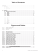
Table of Contents Safety Notes........................................................................................................................................................ 5 1.0 2.0 Introduction................................................................................................................................................ 6 1.1 Parts List..........................................................................................................................................
Round Security Bar Safety Notes Review the drawings and illustrations contained in this manual before proceeding. If there are any questions regarding the safe installation or operation of this product, contact Alpha Technologies or the nearest Alpha representative. Save this document for future reference. To reduce the risk of injury or death, and to ensure the continued safe operation of this product, the following symbols have been placed throughout this manual.
1.0 Introduction Each security bar kit contains the parts and accessories needed to secure one enclosure door. If the enclosure has both a front and back door, it will require two kits, with exception of the FPE. 1.
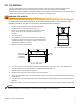
2.0 Installation This procedure applies to each of the supported enclosures. Refer to Section 2.1 Dimensioned Enclosure Drawings for specific information pertaining to the enclosure onto which the kit(s) will be installed. All enclosures require installation of both side brackets and lock brackets. The side brackets hold the security bar, and the lock brackets hold the security lock (refer to Figures 2-3 and Figure 2-4).
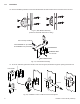
2.0 Installation 12. Use the hardware provided to mount the side brackets and lock brackets to the enclosure and to the door. Fig. 2-3, Side Bracket Assembly (enclosure door/sides removed for clarity) NUT 1/4"-20 (2 PLACES) LOCK WASHER 1/4" (2 PLACES) FLAT WASHER 1/4" (2 PLACES) LOCK BRACKET CARRIAGE BOLT 1/4"-20 X 3/4" ENCLOSURE DOOR LOCK BAR Fig. 2-4, Lock Bracket Assembly 13. To secure, slide lock guard over bracket, insert lock into guard, slide bar through the opening and close lock.
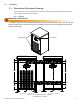
2.0 Installation 2.1 Dimensioned Enclosure Drawings The dimensioned enclosure drawings in this section provide specific hole placement locations for the Security Bar bracket mounting hardware. 2.1.1 CE-3G WARNING! FIRE HAZARD CE Model Enclosures have integrated gas lines near the enclosure door jam. Turn off the gas before installing the enclosure and ensure all drilling locations will not damage the gas lines before proceeding.
2.0 Installation 2.1 Dimensioned Enclosure Drawings, continued 2.1.2 CE-3X2 WARNING! FIRE HAZARD CE Model Enclosures have integrated gas lines near the enclosure door jam. Turn off the gas before installing the enclosure and ensure all drilling locations will not damage the gas lines before proceeding.
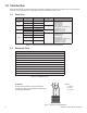
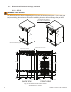
2.0 Installation 2.1 Dimensioned Enclosure Drawings, continued 2.1.3 CE-9G WARNING! FIRE HAZARD CE Model Enclosures have integrated gas lines near the enclosure door jam. Turn off the gas before installing the enclosure and ensure all drilling locations will not damage the gas lines before proceeding. Location of bracket mounting holes 2 1/8" 2 9/16" 33 7/8" 33 7/16" 2 1/8" 2 9/16" 5 11/16" 9 1/16" 11 7/16" 11/16" 1 1/16" 11/16" FRONT VIEW 11 7/16" 11/16" 11/16" BACK VIEW Fig.
2.0 Installation 2.1 Dimensioned Enclosure Drawings, continued 2.1.4 CE-9X2 WARNING! FIRE HAZARD CE Model Enclosures have integrated gas lines near the enclosure door jam. Turn off the gas before installing the enclosure and ensure all drilling locations will not damage the gas lines before proceeding. Location of bracket mounting holes 2 1/8" 2 9/16" 32 7/8" 32 7/16" 2 1/8" 2 9/16" 5 11/16" 9 1/16" 11/16" 11 7/16" 11/16" FRONT VIEW 11/16" 11 15/32" 11/16" 1 1/32" BACK VIEW Fig.
2.0 Installation 2.1 Dimensioned Enclosure Drawings, continued 2.1.5 PN-3 Location of bracket mounting holes 2 1/8" 2 9/16" 25 7/8" 25 7/16" 2 1/8" 2 9/16" 5 11/16" 9 1/16" 11/16" 11 7/16" 11/16" 1 1/16" FRONT VIEW 11 7/16" 11/16" 11/16" BACK VIEW Fig. 2-10, PN-3 Enclosure Hole Locations All dimensions in inches. 745-847-C1-001 Rev.
2.0 Installation 2.1 Dimensioned Enclosure Drawings, continued 2.1.6 PN-4 Location of bracket mounting holes 2 1/8" 2 1/8" 32 7/8" 32 7/16" 2 1/8" 2 9/16" 5 11/16" 9 1/16" 11/16" 11 7/16" 1 1/16" FRONT VIEW 11/16" 11 7/16" 11/16" 11/16" BACK VIEW Fig. 2-11, PN-4 Enclosure Hole Locations All dimensions in inches. 14 745-847-C1-001 Rev.
2.0 Installation 2.1 Dimensioned Enclosure Drawings, continued 2.1.7 UPE-3 Location of bracket mounting holes 2 1/8" 2 9/16" 16 7/8" 16 7/16" 2 1/8" 2 9/16" 10 1/16" 7/16" 7 11/16" 11 7/8" 7/16" FRONT VIEW Fig. 2-12, UPE-3 Enclosure Hole Locations All dimensions in inches. 745-847-C1-001 Rev.
2.0 Installation 2.1 Dimensioned Enclosure Drawings, continued 2.1.8 UPE-M3 Location of bracket mounting holes 2 1/8" 2 9/16" 15 5/8" 15 3/16" 2 1/8" 2 9/16" 9 1/16" 6 11/16" 11 15/16" 7/16" 7/16" FRONT VIEW Fig. 2-13, UPE-M3 Enclosure Hole Locations All dimensions in inches. 16 745-847-C1-001 Rev.
2.0 Installation 2.1 Dimensioned Enclosure Drawings, continued 2.1.9 UPE-6 Location of bracket mounting holes 2 1/8" 2 9/16" 26 7/8" 26 7/16" 2 1/8" 2 9/16" 10 1/16" 7/16" 7 5/8" 11 7/8" 7/16" FRONT VIEW Fig. 2-14, UPE-6 Enclosure Hole Locations All dimensions in inches. 745-847-C1-001 Rev.
2.0 Installation 2.1 Dimensioned Enclosure Drawings, continued 2.1.10 UPE-M6 2 1/8" 2 9/16" 28 1/8" 27 11/16" 2 1/8" 2 9/16" 9 1/16" 7/8" 6 11/16" 11 15/16" 7/8" FRONT VIEW 18 Fig. 2-15, UPE-M6 Enclosure Hole Locations All dimensions in inches. 745-847-C1-001 Rev.
2.0 Installation 2.1 Dimensioned Enclosure Drawings, continued 2.1.11 FPE Location of bracket mounting dimples/drill locations 2 1/8" 2 9/16" 25" 26 7/16" 2 1/8" 2 9/16" 10 1/16" 7 1/2" 7 5/8" 3/4" 17 1/4" 3/4" 18" 28 3/8" FRONT VIEW Fig. 2-16, FPE Enclosure Dimple Locations All dimensions in inches; dimensions are for reference purposes. 745-847-C1-001 Rev.
Alpha Technologies Inc. 3767 Alpha Way Bellingham, WA 98226 United States Tel: +1 360 647 2360 Fax: +1 360 671 4936 Alpha Technologies Ltd. 7700 Riverfront Gate Burnaby, BC V5J 5M4 Canada Tel: +1 604 436 5900 Fax: +1 604 436 1233 Toll Free: +1 800 667 8743 Alpha Industrial Power Inc.