USM2.5 Status Monitor Operator’s and Technical Manual USM2.
Power Alpha Technologies ®
™ USM2.5 Staus Monitoring Module Operator’s and Technical Manual 704-683-B0-004 Rev. D— © 2006 by Alpha Technologies, Inc. Effective: April, 2006 Statement of Intended Usage Alpha denies responsibility for any damage or injury involving its enclosures, power supplies, generators, batteries, or other hardware when used for an unintended purpose, installed or operated in an unapproved manner, or improperly maintained. Information on CE Compliance Alpha Technologies Communications Module, model USM 2.
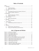
Table of Contents Safety ................................................................................................................... 5 1. Introduction ...................................................................................................... 7 1.1 USM2.5 Introduction .............................................................................. 7 1.2 Identification of USM2.5 ........................................................................ 7 2. Installation .......................
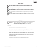
Safety Safety Notes This symbol identifies conditions and actions that pose a hazard to the user. This symbol cautions the user of conditions and actions that may damage the power supply or associated equipment. This symbol identifies a condition that may be corrosive to equipment and parts, or damaging to skin. This symbol identifies a condition in which it is required to recycle discarded materials. This symbol identifies a situation in which static-sensitive components are present.
Safety Cautions NOTE: Equipment or parts may be damaged or cause damage if used or installed improperly. To avoid damage: 6 • Prior to installation, verify that the AC input voltage to the enclosure and its equipment match with respect to voltage and frequency. • Prior to installation, verify that the output voltage from the enclosure or its equipment match the voltage requirements of the connected equipment (load).
1. Introduction 1.1 USM2.5 Introduction This Operator’s and Technical Manual will cover the installation, signal definition, operation, and basic troubleshooting for the USM2.5 when used with the Alpha XM Series 2 Power Supply. The USM2.5 card is a logic controller PCB which may be used to upgrade any XM Series 2 Power Supply for the purpose of remote status monitoring. As part of the Communications Module upgrade, the USM2.5 connects directly to the XM2’s Inverter Module via an 18 pin jumper.
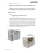
2. Installation 2.1 Inverter Module Removal and Installation The XM Series 2 Power Supply comes with a field-replaceable Inverter Module, containing the inverter, battery charger and control logic circuitry. The Inverter Module is designed to accept USM2.5 plug-in logic upgrades to facilitate remote status monitoring. The Inverter Module can be removed while the power supply is running on line power. With the Inverter Module removed, the power supply will continue to operate in a non-standby mode.
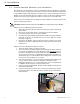
2. Installation 2.2 USM2.5 Installation The optional USM2.5 status monitoring upgrade plugs into the XM Series 2 Inverter Module. The USM2.5 can be configured for various status monitoring interfaces by setting the DIP switch. Status monitoring interfaces are listed according to their manufacturer, along with the associated parts in Section 3.1. The USM2.5 also accommodates a tamper switch assembly to indicate unauthorized enclosure entries. CAUTION: The USM2.
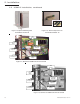
2. Installation 2.2 USM2.5 Installation , continued Figure 2-2; Optional Blanking Plate Part Number 745-419-20 Figure 2-3; 2X9 Pin Strip Connector Part Number 540-581-10 PEM Fastener Tamper Switch Configuration Switch SW1 External Transponder VOUT Scaled DC Adjust Pot. System Communication Pin 1 Indicator Figure 2-4; Old Version USM2.5 Front Panel & PCB (PEM Fastener) Tamper Switch Configuration Switch SW1 External Transponder VOUT Scaled DC Adjust Pot.
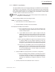
3. Configuration 3.1 USM2.5 Configuration (V Models) The following information affects the use of the USM2.5 module on all V5 and VP versions of the XM2 Power supply. It should be referenced in place of the information contained in the relevant sections of this manual. AC Output Current Monitoring On V5 And VP Models • The AC current from output 1 of the Power supply is present on Pin 13 of the USM2.5 transponder connector J3.
3. Configuration 3.2 USM2.5 Configuration Refer to the following chart to determine your USM2.5 model USM2-5 Model: USM2.5 USM2.5 22 USM2.5 48 USM2.
3. Configuration 3.2 USM2.5 Configuration, continued Figure 3-1; USM2.5 Switch Location (Old Version ) Figure 3-2; USM2.5 Switch Location (New Version ) Always verify USM2.5 configuration especially after upgrading or modifying the XM Series 2 Power Supply. Function Switch SW1 Reference The following information describes each switch position (1–8) for the DIP switch SW1. SW1 is an eight switch component used primarily to select analog scaling and digital signal polarity for the USM2.5 card.
3. Configuration 3.2 USM2.5 Configuration, continued SW1 (4) and (8): Auxiliary DC Voltage Select SW1, position 4 and 8 are used to select the voltage of the AUX DC delivered to the transponder, measured at J4 pin 2.
4. Signal Definitions 4.1 USM2.5 Signal Definition IMPORTANT NOTE: For the USM2.5 to function correctly, OUTPUT (N) must be grounded to the chassis of the XM Series 2. In a typical installation, this is automatically done through the SPI, but during bench testing this connection will have to be manually made by placing a jumper between the power supply Output Neutral and chassis ground. HIGH is typically defined as AUX DC Voltage ± 10% (+5VDC, +15VDC, or +24VDC as set by configuration).
4. Signal Definitions 4.1 USM2.5 Signal Definition, continued This Section provides specific details of all signals (input and output) provided on the XPDR and TMPR Connectors when set up as a USM2.5 (default setting).
4. Signal Definitions 4.1 USM2.5 Signal Definition, continued Name: Pin: Signal Type: Referenced to: Description: Parameters: How to test: Name: Pin: Signal Type: Referenced to: Description: Parameters: How to test: Name: Pin: Signal Type: Referenced to: Description: Active Means: Active State: Inactive Means: Inactive State: How to Test: 704-683-B0-004, Rev. D AC Output Voltage J4-4 USM2.
4. Signal Definitions 4.1 USM2.5 Signal Definition, continued Name: Pin: Signal Type: Referenced to: Description: Active Means: Active State: Inactive Means: Inactive State: How to Test: Tamper Switch Status J4-7 USM2.5 Discrete Output Common (J4-1, J4-12) USM2.5 output indicates the current state of the XM2’s enclosure tamper switch. This is a non-latching type alarm. The enclosure door is opened or the tamper switch is disconnected.
4. Signal Definitions 4.1 USM2.5 Signal Definition, continued Name: Pin: Signal Type: Referenced to: Description: Active Means: Active State: Inactive Means: Inactive State: NOTE: Output Fail Alarm J4-10 USM2.5 Discrete Output Common (J4-1, J4-12) This USM2.5 signal indicates the state of the AC output. A nonlatching signal, the Output Alarm will match the state of the power supply output in real-time. The XM2’s AC output has failed. LOW The XM2’s AC output is OK.
4. Signal Definitions 4.1 USM2.5 Signal Definition, continued Name: Pin: Signal Type: Referenced to: Description: Common J4-12 Ground reference / return N/A Ground / return reference for ALL signals (analog, input & output) on the USM2.5. Same as J4 pin 1 and J5 pin 2. Name: Pin: Signal Type: Referenced to: Description: Output Current #2 J4-13 (J4-8 for ONU equipped units) USM2.5 Analog Output #2 Common (J4-1, J4-12) This USM2.5 analog output is a DC approximation of the total XM2 AC output #2 current.
5. Operation 5.1 USM2.5 Operations USM2.5 Start up and Test Procedure The XM Series 2 power supply should be fully tested before attempting any USM2.5 operations. Refer to the XM Series 2 technical manual for details. Once the power supply has been verified as “GOOD” the USM2.5 can then be tested as follows: 1. Verify the USM2.5 installation by checking: • Configuration settings of switch SW1. • USM2.
6. Troubleshooting 6.1 Troubleshooting the Communications Link Occasionally the communications link between the XM Series 2 power supply and the headend site may appear to break down. Updates to and from the power supply may not take place, or data received may be faulty. When this happens, isolate and correct the failed elements in a precise fashion to avoid extended troubleshooting times or the possibility spreading a potential failure from site to site.
7. Parts 7.1 Par ts The following parts can be purchased by calling your local Alpha representative: Part Name: Alpha Part Number: Ribbon Cable 874-992-20 2 x 9 Header 540-581-10 Hardware Kit Includes: 2 x 9 Header Plastic Standoffs Screws 745-153-22 Sheet Metal Kit Includes: Faceplate with silkscreen Mounting Hardware 745-153-21 704-683-B0-004, Rev.
8. Reference 8.1 USM2.5 Signals, Quick Reference PIN Signal Name Type 2 Tamper Switch Return (Ground) Return for Tamper Switch input to USM2-5 (same as J4 pins 1 and 12) 1 Tamper Switch Discrete (In) Tamper Switch input to USM 13 Output Current 2 (Output Current 1 for ONU equipped units) Analog Scaled analog representation of UPS output current #2. Scaling: 0.4 VDC per Amp output 12 Ground Ground Ground reference for all signal and power (same as J5 pin 2 and J4 pin 1).
8. Reference 8.2 Testing and Troubleshooting, Quick Reference USM2.5 Start up and Test Procedure The XM Series 2 power supply should be fully tested before attempting any USM2.5 operations. Refer to the XM Series 2 technical manual for details. Once the power supply has been verified as “GOOD” the USM2.5 can then be tested as follows: 1. Verify the USM2.5 installation by checking: • Configuration settings of switch SW1. • USM2.
Power ® Alpha Technologies Alpha Technologies 3767 Alpha Way Bellingham, WA 98226 USA Tel: +1 360 647 2360 Fax: +1 360 671 4936 Web: www.alpha.com Alpha Technologies Ltd. 4084 McConnell Court Burnaby, BC, V5A 3N7 CANADA Tel: +1 604 430 1476 Fax: +1 604 430 8908 Alpha Technologies Europe Ltd.