
Manual

3. Configuration
704-683-B0-004, Rev. D
14
3.2 USM2.5 Configuration,
continued
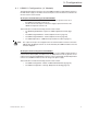
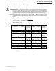
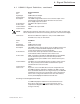
SW1 (4) and (8): Auxiliary DC Voltage Select
SW1, position 4 and 8 are used to select the voltage of the AUX DC delivered to the
transponder, measured at J4 pin 2.
SW1 (4) SW1 (8)Aux DC Voltage
OFF OFF + 5 VDC
ON OFF + 24 VDC
OFF ON + 15 VDC
ON ON N/A Incorrect Switch Setting
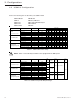
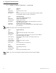
SW1 (5) and (6): Output Voltage AC or DC Scaling Select
SW1, position 5 and 6 is used to select the AC or DC representation of the XM
Series 2 AC OUTPUT VOLTAGE measurement, measured at J4 pin 4.
SW1 (5) SW1 (6)Output Volts (DC)
OFF OFF N/A No output at J4 pin 4
OFF ON 0.5 VAC Per Volt AC Output
ON OFF 0.15 VDC Per Volt AC Output
ON ON N/A Incorrect Switch Setting
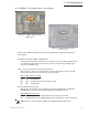
NOTE: DC setting accuracy can be calibrated by adjusting the front panel potentiometer
(see Fig 2-4).
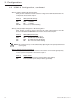
SW1 (7): Tamper Status Polarity Select
SW1, position 7 is used to select between inverted or non-inverted signal polarity
for the system’s transponder measured at J4 pin 7.
SW1 (7) Tamper Status
OFF Not inverted (switch opens; Tamper Status goes HIGH)
ON Inverted (switch opens; Tamper Status goes LOW)