
Manual

4. Signal Definitions
15
704-683-B0-004, Rev. D
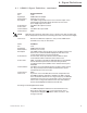
IMPORTANT NOTE: For the USM2.5 to function correctly, OUTPUT (N) must be grounded to
the chassis of the XM Series 2. In a typical installation, this is automatically done
through the SPI, but during bench testing this connection will have to be manually made
by placing a jumper between the power supply Output Neutral and chassis ground.
HIGH is typically defined as AUX DC Voltage ± 10% (+5VDC, +15VDC, or +24VDC as set by
configuration). Voltage exceeding AUX DC is abnormal, but will not likely damage the
USM2.
(90%AUX DC < HIGH < AUX DC)
LOW is typically defined as 0VDC, however any nonnegative voltage between 0VDC and +1VDC
will be accepted by the USM2.5 as LOW.
(0VDC < LOW < 1VDC)
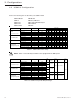
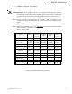
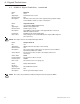
4.1 USM2.5 Signal Definition
AC Input Voltage 120VAC N/A N/A N/A
AC Input Voltage 240VAC N/A N/A N/A
Approx.
2.7VAC*
USM2.5
Internal
Acterna
+24VDC
43.5VAC
20.7VDC
2.8VDC
Sample 1 XMS2
USM2.5
External
Acterna
USM2.5
AM
USM2.5
TG
Auxiliary DC Out N/A +5VDC +15VDC +5VDC
AC Output Voltage 63VAC 31.5VAC 31.5VAC 9.45VDC
Battery Voltage
(36 VDC Nominal)
41.4VDC 20.7VDC 20.7VDC 4.14VDC
Output Current 7A 2.8VDC 2.8VDC 2.8VDC
Sample 2 XMS2
USM2.5
External
Acterna
USM2.5
External
AM
USM2.5
External
TG
Auxiliary DC Out N/A +5VDC +15VDC +5VDC
AC Output Voltage 87VAC 43.5VAC 43.5VAC 13.05VDC
Battery Voltage
(36 VDC Nominal)
39.6VDC 19.8VDC 19.8VDC 3.96VDC
Output Current 14A 5.6VDC 5.6VDC 5.6VDC
USM2.5
Internal
Acterna
+24VDC
31.5VAC
20.7VDC
2.8VDC
Approx.
2.5VAC*
* Input voltages will measure approximately 2.7 VAC for 240 VAC input and 2.5 VAC for 120 VAC input.
Table 4-1; USM2.5 Output Scaling Samples