
Manual

4. Signal Definitions
16
704-683-B0-004, Rev. D
4.1 USM2.5 Signal Definition,
continued
This Section provides specific details of all signals (input and output) provided on the XPDR
and TMPR Connectors when set up as a USM2.5 (default setting).
Name: Common
Pin: J4-1
Signal Type: Ground reference / return
Referenced to: N/A
Description: Ground / return reference for ALL signals (analog, input & output) on
the USM2.5. Same as pins J4-12 and J5-2.
Name: Auxiliary DC Out
Pin: J4-2
Signal Type: Power
Referenced to: Common (J4-1, J4-12)
Description: This pin provides power for transponder pull up resistors as needed.
Auxiliary DC Out is not intended to provide complete logic &
transceiver power to the transponder, except in the case of internal
transponders
Parameters: Current drawn from this pin should NOT exceed 100mA under any
circumstance. Auxiliary DC Out is overcurrent protected by the
foldback of the switching power supply
How to test: Verify voltage on pin #2 is +5VDC, +15VDC, or +24VDC; (all within
10% tolerance) as set by configuration.
Name: Standby / Line Fail
Pin: J4-3
Signal Type: USM2.5 Discrete output
Referenced to: Common (J4-1, J4-12)
Description: This USM2.5 output indicates the state of the XM2 inverter.
Active Means: The XM2’s inverter is ON, and/or the AC line input has failed.
Active State: LOW
Inactive Means: The XM2’s inverter is NOT ON.
Inactive State: HIGH
How to test: With the XM2’s inverter ON, verify LOW on J4-3.
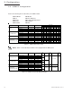
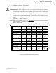
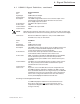
Tamper Switch Input
Transponder I/O
Tamper switch return (GND)
Tamper switch sensor
2
1
Output current 2 13
Ground 12
Test / Reset 11
Output fail 10
AC input voltage 9
Output current 1 8
Tamper status
7
Equipment Fail
6
Battery voltage
5
AC output voltage
4
Standby / Line fail
3
Aux DC output
2
Ground
1
Pin 1
DC Scaling Adjust
J5
J4
Output current 1
for ONU equipped units
Output current 2
for ONU equipped units
Figure 4-1; USM2.5 Signal Connections