
Manual

4. Signal Definitions
20
704-683-B0-004, Rev. D
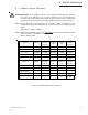
4.1 USM2.5 Signal Definition,
continued
Name: Common
Pin: J4-12
Signal Type: Ground reference / return
Referenced to: N/A
Description: Ground / return reference for ALL signals (analog, input & output)
on the USM2.5. Same as J4 pin 1 and J5 pin 2.
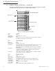
Name: Output Current #2
Pin: J4-13 (J4-8 for ONU equipped units)
Signal Type: USM2.5 Analog Output #2
Referenced to: Common (J4-1, J4-12)
Description: This USM2.5 analog output is a DC approximation of the total
XM2 AC output #2 current.
Parameters: 0.4VDC per AC ampere XM2 output.
How to Test: Verify voltage on J4-13 is 0.4VDC per AC ampere XM2 output #2
(±5% tolerance).
NOTE: The output current scale is dependant upon SW1-3
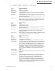
Name: Tamper Switch In
Pin: J5-1
Signal Type: USM2.5 Discrete Input (dry contact switch)
Referenced to: J5-2
Description: Dry contact tamper switch input. Left open circuit, this USM2.5
input will be pulled up to +5VDC.
Active Means: The enclosure’s door is open or the tamper switch is not
connected.
Active State: OPEN
Inactive Means: The enclosure’s door is closed.
Inactive State: SHORT
How to test: See ‘How to Test’ for J4-7 (page 17).
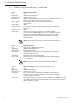
Name: Tamper Switch Return
Pin:J5-2
Signal Type: Ground Reference/return
Referenced to: N/A
Description: Return / ground for Tamper switch.
NOTE: ALL values are provided for troubleshooting and reference purposes ONLY.