Acterna Embedded Transponder Addendum to USM2.
Power Alpha Technologies. Protecting The Power in Communications.
™ Acterna Embedded Transponder Installation Manual 018-041-C0-002, Rev B Effective Date: July, 2002 © 2002 by Alpha Technologies NOTE: Photographs contained in this manual are for illustrative purposes only. These photographs may not exactly match your installation. NOTE: Review the drawings and illustrations contained in this manual before proceeding. If there are questions regarding the safe operation of this powering system, please contact Alpha Technologies or your nearest Alpha representative.
Table of Contents 1. Installation .................................................................................................................5 1.1 1.2 1.3 1.4 1.5 1.6 Installation in an XM Series 2 Power Supply ......................................... 5 Transponder Inputs and Outputs ............................................................ 7 Battery Monitor Connections ................................................................. 8 Generator Connection .......................................
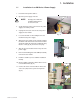
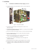
1. Installation 1.1 Installation in an XM Series 2 Power Supply 1. Record the transponder address. 2. Open the power supply enclosure. NOTE: Disconnect here Backup power will not be available while batteries are disconnected. 3. Set the battery breaker on the front of the power supply to the OFF position. 4. Unplug all connectors on the front of the power supply inverter module. 5. Loosen the thumb screws holding the inverter module into the power supply. Fig. A 6.
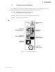
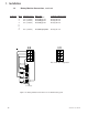
1. Installation 1.1 Installation in an XM Series 2 Power Supply, continued 12. Using the two captive screws just behind the face plate, secure the transponder to the inverter module. 8 Position DIP Switch Captive screw 10 Position Jumper Captive screw Figure 1-1 Transponder Installation 13. Verify that the 10 position jumper on the transponder is set to the correct battery pack voltage. 14. Verify that the 8 position DIP Switch on the USM2.5 is set correctly. Refer to the USM2.
1. Installation 1.2 Transponder Inputs and Outputs The following section describes the input and output connections on the transponder. Refer to the sections indicated below for a brief description and pin-out of the connector. CPU LED Flashing: Normal operation, P-Code running. Solid: Initial start-up, R-Code running. RX LED Data is being recieved from the HEC (Head End Controller). TX LED Data is being sent to the HEC. CPU CPU / Serial Port Activity RESET RX A/B TX GEN 1 Section 1.
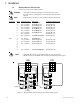
1. Installation 1.3 Battery Monitor Connections Refer to section 4 for wire kit part numbers. WARNING: Verify that the 10 Position jumper on the transponder is set to the proper battery voltage prior to connecting the battery monitor wire kit. A maximum of 12 batteries can be monitored by the transponder.
1. Installation Battery Monitor Connections, continued 1.
1. Installation 1.
1. Installation 1.
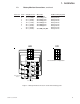
1. Installation Battery Monitor Connections, continued 1.
1. Installation Battery Monitor Connections, continued 1.
1. Installation Battery Monitor Connections, continued 1.
1. Installation 1.4 Generator Connection The Generator Connector provides the Transponder with alarms and status signals. Control signals can also be sent to the generator for test and Run / Stop. Refer to the ECM operation and maintenance manual for further information on the generator connections.
1. Installation 1.5 Generator Ignition Battery Connection The Generator Battery Connector provides the transponder with voltage information on the Ignition Battery and optional ambient temperature probe.
1. Installation 1.6 COMM and RF Connections The COMM connector allows the technician to bypass the RF modulator and communicate with the transponder through a PC's RS-232 serial port. The RF connector is the primary I/O port to the head-end modem.
2. Specifications 2.
3. Troubleshooting 3.1 Testing and Troubleshooting Testing All testing shall be performed via Acterna's NetMentor and Test2way software. Refer to software manufacturer's instructions. Troubleshooting Problem: Solution: Missing parts or shipping damage. Contact Alpha Technologies at: Alpha Technologies, Inc. 3767 Alpha Way Bellingham, WA. 98226 360-647-2360 Problem: Solution: Unable to communicate with transponder. Check port assignments, cables, and RPS name / port.
4. Part Numbers 4.1 Cable Kit Options Combination Kits Part Number 745-181-20 745-197-23 745-197-22 745-198-21 745-180-20 745-182-20 745-246-20 745-197-20 745-197-21 745-198-20 745-245-20 Description Combo Batt Sense Kit, 1x36V, w/ Gen Interface Combo Batt Sense Kit, 2x36V, w/ 35' Ext. Combo Batt Sense Kit, 3x36V, w/ 2x35' Ext. Combo Batt Sense Kit, 3x36V, 1 @ 6', 2 @ 9' Combo Batt Sense Kit, 4x36V, w/ 2x35' Ext.
Power www.alpha.com Protecting The Power in Communications. Corporate Alpha Technologies 3767 Alpha Way Bellingham, WA 98226 USA Tel: (360) 647-2360 Fax: (360) 671-4936 Web: www.alpha.com Alpha Technologies Ltd. 4084 McConnell Court Burnaby, BC, V5A 3N7 CANADA Tel: (604) 430-1476 Fax: (604) 430-8908 Alpha Technologies Europe Ltd.