TM USM2.
Power ® Alpha Technologies 2 018-041-C0-003 Rev.
™ USM2.5 Status Monitoring Module with Acterna Embedded Transponder Technical Manual 018-041-C0-003 Rev. C — © 2003 by Alpha Technologies, Inc. Effective: September 2003 Statement of Intended Usage Alpha denies responsibility for any damage or injury involving its enclosures, power supplies, generators, batteries, or other hardware when used for an unintended purpose, installed or operated in an unapproved manner, or improperly maintained.
Table of Contents Safety ................................................................................................. 5 1. Installation ..................................................................................... 9 1.1 1.2 1.3 1.4 1.5 1.6 Installation in an XM Series 2 Power Supply .......................................... 9 Transponder Inputs and Outputs .......................................................... 11 Battery Monitor Connections ................................................
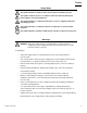
Safety Safety Notes This symbol identifies conditions and actions that pose a hazard to the user. This symbol cautions the user of conditions and actions that may damage the power supply or associated equipment. This symbol identifies a condition that may be corrosive to equipment and parts, or damaging to skin. This symbol identifies a condition in which it is required to recycle discarded materials. This symbol identifies a situation in which static-sensitive components are present.
Safety Warnings, continued • Avoid any contact with gelled or liquid emissions from a valve-regulated lead-acid (VRLA) battery. Emissions contain dilute sulfuric acid which is harmful to the skin and eyes. Emissions are electrolytic, which are electrically conductive and are corrosive. Follow the Chemical Hazards notes if contact occurs. • • Do not smoke or introduce sparks in the vicinity of a battery.
Safety Battery Safety Lead-acid batteries contain dangerous voltages, currents and corrosive material. Battery installation, maintenance, service and replacement must be performed by authorized personnel only. Any gelled or liquid emissions from a Valve-Regulated lead-acid (VRLA) battery contain dilute sulfuric acid, which is harmful to the skin and eyes. Emissions are electrolytic, which are electrically conductive and corrosive. Chemical Hazards To avoid injury: • • • • • • • 018-041-C0-003 Rev.
Safety Maintenance Guidelines The battery maintenance instructions listed below are for reference only. Battery manufacturer’s instructions for transportation, installation, storage or maintenance take precedence over these instructions. • To prevent damage inspect batteries every 3 months for: -Signs of battery cracking, leaking or swelling. The battery should be replaced immediately by authorized personnel using a battery of the identical type and rating. -Signs of battery cable damage.
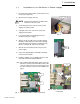
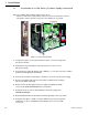
1. Installation 1.1 Installation in an XM Series 2 Power Supply 1. Record the transponder address (located on the sheet metal of the front panel). Disconnect here 2. Open the power supply enclosure. NOTE: Backup power will not be available while batteries are disconnected. 3. Set the battery breaker on the front of the power supply to the OFF position. 4. Unplug all connectors on the front of the power supply inverter module. Fig. A 5.
1. Installation 1.1 Installation in an XM Series 2 Power Supply, continued 10(b). For a USM2.5 with two ribbon cable sockets (J2, J3): Attach one end of the 3-position ribbon cable to the connector (JP2) at the top of the transponder, and the other two connectors to the USM2.5 (J2, J3). (fig. D) 8 Position DIP Switch Captive screw 10 Position Jumper Captive screw Figure 1-1 Transponder Installed 11. Using the two captive screws just behind the face plate, secure the transponder to the inverter module.
1. Installation 1.2 Transponder Inputs and Outputs The following section describes the input and output connections on the transponder. Refer to the sections indicated below for a brief description and pin-out of the connector. CPU LED Flashing: Normal operation, P-Code running. Solid: Initial start-up, R-Code running. RX LED Data is being received from the HEC (Head End Controller). TX LED Data is being sent to the HEC. CPU CPU / Serial Port Activity RESET RX A/B TX GEN 1 Section 1.
1. Installation 1.3 Battery Monitor Connections Refer to section 4 for wire kit part numbers. WARNING: Verify that the 10 Position jumper on the transponder is set to the proper battery voltage prior to connecting the battery monitor wire kit. A maximum of 12 batteries can be monitored by the transponder.
1. Installation Battery Monitor Connections, continued 1.
1. Installation 1.
1. Installation 1.
1. Installation Battery Monitor Connections, continued 1.
1. Installation Battery Monitor Connections, continued 1.
1. Installation Battery Monitor Connections, continued 1.
1. Installation 1.4 Generator Connection The Generator Connector provides the Transponder with alarms and status signals. Control signals can also be sent to the generator for test and Run / Stop. Refer to the ECM operation and maintenance manual for further information on the generator connections.
1. Installation 1.5 Generator Ignition Battery Connection The Generator Battery Connector provides the transponder with voltage information on the Ignition Battery and optional ambient temperature probe.
1. Installation 1.6 COMM and RF Connections The COMM connector allows the technician to bypass the RF modulator and communicate with the transponder through a PC's RS-232 serial port. The RF connector is the primary I/O port to the head-end modem.
2. Specifications 2.
3. Troubleshooting 3.1 Important Troubleshooting Notes Always troubleshoot communication problems before working on battery-related and/or generatorrelated problems. The embedded transponder runs off of the power supply’s USM2.5 logic voltages, and does not require the sensing cables (from the batteries or the generator) to communicate. 1. USM2.5 Switch Set-up: The 8 position “DIP” switch on the USM2.5 board must be set correctly. See the complete chart in the USM2.
3. Troubleshooting 3.1 Important Troubleshooting Notes, continued If there are two power supplies in the same enclosure, make sure that the interface cable from the generator ECM is connected to the correct embedded transponder. 4.
3. Troubleshooting 3.2 Troubleshooting Specifics and Testing Troubleshooting Problem: Solution: Missing parts or shipping damage. Contact Alpha Technologies at: Alpha Technologies, Inc. 3767 Alpha Way Bellingham, WA. 98226 360-647-2360 Problem: Solution: Unable to communicate with transponder. Check port assignments, cables, and RPS name / port. Problem: Solution: Incorrect device type selected when adding unit. Check the device type in the Device Configuration screen (CheetahNet).
4. Part Numbers 4.1 Cable Kit Options Combination Kits Part Number 745-181-20 745-197-23 745-197-22 745-198-21 745-180-20 745-182-20 745-246-20 745-197-20 745-197-21 745-198-20 745-245-20 Description Combo Batt Sense Kit, 1x36V, w/ Gen Interface Combo Batt Sense Kit, 2x36V, w/ 35' Ext. Combo Batt Sense Kit, 3x36V, w/ 2x35' Ext. Combo Batt Sense Kit, 3x36V, 1 @ 6', 2 @ 9' Combo Batt Sense Kit, 4x36V, w/ 2x35' Ext.
Power ® Alpha Technologies Corporate Alpha Technologies 3767 Alpha Way Bellingham, WA 98226 USA Tel: (360) 647-2360 Fax: (360) 671-4936 Web: www.alpha.com Alpha Technologies Ltd. 4084 McConnell Court Burnaby, BC, V5A 3N7 CANADA Tel: (604) 430-1476 Fax: (604) 430-8908 Alpha Technologies Europe Ltd.