
Manual

4
018-041-C0-003 Rev. C
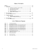
Table of Contents
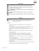
Safety ................................................................................................. 5
1. Installation ..................................................................................... 9
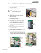
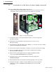
1.1 Installation in an XM Series 2 Power Supply .......................................... 9
1.2 Transponder Inputs and Outputs.......................................................... 11
1.3 Battery Monitor Connections ............................................................... 12
1.4 Generator Connection ......................................................................... 19
1.5 Generator Ignition Battery Connection ................................................. 20
1.6 COMM and RF Connections................................................................ 21
2. Specifications..............................................................................22
2.1 Channel Parameters............................................................................ 22
3. Troubleshooting ..........................................................................23
3.1 Important Troubleshooting Notes ......................................................... 23
3.2 Troubleshooting Specifics and Testing ................................................. 25
4. Part Numbers .............................................................................. 26
4.1 Cable Kit Options ................................................................................ 26
Figure 1-1 Transponder Installation .......................................................................................10
Figure 1-2 Input / Output Connections .................................................................................. 11
Figure 1-3 Battery Monitor Connections for three 48Vdc battery packs ................................12
Figure 1-4 Battery Monitor Connections for two 48Vdc battery packs ................................... 13
Figure 1-5 Battery Monitor Connections for one 48Vdc battery pack ....................................14
Figure 1-6 Battery Monitor Connections for one 36Vdc battery pack ....................................15
Figure 1-7 Battery Monitor Connections for two 36Vdc battery packs ................................... 16
Figure 1-8 Battery Monitor Connections for three 36Vdc battery packs ................................17
Figure 1-9 Battery Monitor Connections for four 36Vdc battery packs ..................................18
Figure 1-10 Generator Monitor Connections ...........................................................................19
Figure 1-11 Generator Ignition Battery Connection ................................................................. 20
Figure 1-12 COMM / RF Connections .................................................................................... 21
Figure 3-1 Battery String Example........................................................................................24
Table 2-1 Channel Parameters ............................................................................................ 22
Table 4-1 Cable kit part numbers ........................................................................................ 26
List of Tables and Figures