VMX Standby Power Supply Technical Manual VMX Series Standby Power Supply Effective: October, 2007 Alpha Technologies
Power Alpha Technologies ®
VMX Standby Power Supply 017-940-B0-001, Rev A Effective Date: October, 2007 Copyright© 2007 Alpha Technologies, Inc. member of The GroupTM NOTE: Photographs contained in this manual are for illustrative purposes only. These photographs may not match your installation. NOTE: Operator is cautioned to review the drawings and illustrations contained in this manual before proceeding.
Table of Contents Safety Notes .......................................................................................................................... 7 Utility Power Connection Notes .................................................................................. 9 Signal Ground ............................................................................................................11 1.0 2.0 3.0 4.0 5.0 4 Introduction to the VMX Power Supply ..................................................
6.0 7.0 5.5 Providing Power via External Source............................................................. 46 5.6 5.5.1 DC Powering ....................................................................................... 46 5.5.2 AC Powering ....................................................................................... 46 5.5.3 Using a Truck-mounted Inverter or Generator .................................... 47 Resumption of Utility Power .......................................................
List of Figures and Tables Fig. 1-1, VMX Power Supply ............................................................................................... 12 Fig. 1-2, VMX Terminal Block Overview .............................................................................. 13 Fig. 1-3, Inverter Overview .................................................................................................. 14 Fig. 2-1, Charger Modes......................................................................................
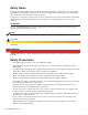
Safety Notes Review the drawings and illustrations contained in this manual before proceeding. If there are any questions regarding the safe installation or operation of this product, contact Alpha Technologies or the nearest Alpha representative. Save this document for future reference. To reduce the risk of injury or death, and to ensure the continued safe operation of this product, the following symbols have been placed throughout this manual. Where these symbols appear, use extra care and attention.
Safety Precautions, continued • Do not allow live battery wires to contact the enclosure chassis. Shorting battery wires can result in a fire or possible explosion. • Always replace batteries with those of an identical type and rating. Never install old or untested batteries. • Avoid using uninsulated tools or other conductive materials when handling batteries or working inside the enclosure. • Remove all rings, watches and other jewelry before servicing batteries.
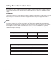
Utility Power Connection Notes ATTENTION: Connecting to the utility should be performed only by qualified service personnel and in compliance with local electrical codes. Connection to utility power must be approved by the local utility before installing the power supply. ATTENTION: UL and NEC require that a service disconnect switch (UL listed) be provided by the installer and be connected between the power source and the VMX Power Supply.
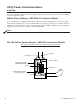
Utility Power Connection Notes ATTENTION: In most cases, the following configurations qualify for service entrance use when wiring a duplex receptacle to a service disconnect. Other codes may also apply. Always contact your local utility to verify that the wiring conforms to applicable codes. 240Vac Service Entrance, VMX 225V, U.S. Domestic Models These configurations are equipped with a 240Vac duplex receptacle to provide power to the power supply and peripheral equipment.
Grounding Connection Notes In order to provide a ready, reliable, source of backup power, it is necessary to establish a grounding system that provides for the safety of service personnel and for the proper operation and protection of equipment within the network. Safety Ground The safety ground is a two-part system. The first part is a return path for stray current back to the input breaker, and the second is a return path from the Alpha enclosure to a second ground rod.
1.0 Introduction to the VMX Power Supply The Alpha family of VMX Uninterruptible Power Supplies is designed for powering signal processing equipment in cable television and broadband LAN distribution systems. The VMX provides a critical load with current-limited, regulated, AC power that is free of spikes, surges, sags and noise. During AC line operation, AC power entering the power supply is converted into a quasi square wave and is regulated by a ferroresonant transformer at the required output voltage.
1.0 Introduction to the VMX Power Supply, continued 1.1 Connections Overview Below is a brief description of each terminal. Connections: • AUX OUT (Auxiliary Output): The Auxiliary Output is an uninterruptible supply of power that can be used to power external devices such as cable modems or ethernet hubs. The auxiliary output is rated at 220V 150W and uses a 2A 250V fast blow fuse (Alpha P/N 460-157-19).
1.0 Introduction to the VMX Power Supply, continued 1.2 Inverter Overview The inverter provides uninterrupted power to the ferroresonant transformer (via the batteries) during line failures. During line operation, the inverter charges the batteries using a threestage (Bulk, Accept, and Float) charger.
1.0 Introduction to the VMX Power Supply, continued 1.3 Optional Status Monitoring Modules The VMX Power Supply supports a number of Alpha Technologies communications modules. The modules may be ordered factory-installed or as user-installed field upgrades. CAUTION! Handle these modules with extreme care. Circuit boards and logic upgrades are static-sensitive and susceptible to damage.
1.0 Introduction to the VMX Power Supply, continued 1.4 Optional Features The following options can be factory installed, or upgraded in the field by the user: Local and Remote Indicator (LRI) The LRI (red) lamp is located on the outside of pole-mount enclosures. During normal AC line operation, the LRI remains off. The LRI comes on only when the power supply is running in Standby Mode. Whenever a fault is detected during self-test, the LRI flashes to indicate that service is required.
2.0 Theory of Operation 2.1 AC (Line) Operation During AC line operation, utility power is routed into the primary winding of the ferroresonant transformer through the contacts of the transfer isolation relay. At the same time, power is directed to the rectifier circuitry in the inverter which provides power for the control circuitry. The bidirectional inverter also serves as a battery charger during AC line operation.
2.0 Theory of Operation, continued 2.3 Charger Operation The VMX Power Supply uses a three-stage, temperature-compensated battery charger. During AC line operation, the inverter winding on the ferroresonant transformer feeds the charger circuit which provides BULK, ACCEPT, and FLOAT charge voltages to the batteries.
,(& ,QSXW &RQQHFWRU &KDVVLV *URXQG 6WXG %URZQ %OXH *UHHQ )+ @ $X[ 2XWSXW )XVH >)+ @ >3 @ >3 @ >3 @ >3 @ >3 @ >3 @ ,QSXW ZLQGLQJ 3 3 3 3 >3 @ >3 @ >3 @ >3 @ 3 3 3 3 3 3 3 3 3 3 3 3 3 3 3 029 029 59 59 029 59 . ,VRODWLRQ 5HOD\ . 7DS 6ZLWFKLQJ 5HOD\ .
3.0 Installation CAUTION! Refer to the Safety Precautions, Utility Power Connection Notes, and Grounding Connection Notes (pages 7-12) prior to installation. To Ensure Operator Safety: • Only qualified personnel should install the power supply in accordance with all applicable electrical codes. • Use eye protection whenever working with batteries. • Use only sealed, lead-acid type batteries with a minimum rating of 55Ah (gelled-electrolyte or equivalent).
3.0 Installation, continued 3.1 Installation Procedure The VMX Power Supply has been designed for shelf mounting in the horizontal configuration or wall-mounting in the vertical configuration. 1. Before installing the power supply, inspect for damage, loose connectors, or other potential failures. Correct discrepancies before proceeding. 2. For horizontal configurations, place the VMX Power Supply on the appropriate enclosure mounting shelf.
3.0 Installation, continued 3.2 Service Power Inserter Connections SPI Connection Procedure: 1. Ensure the SPI is unplugged from the power supply prior to removing cover. 2. Remove the two screws holding the cover to the SPI’s chassis. 3. Remove the SPI cover, exposing the circuit board and seizure screw assembly. 1 Seizure Screw Assembly 2 3 Fig. 3-1, SPI Cover Removal 4. Insert the coaxial termination into the output port on the bottom of the SPI and tighten the nut snug. 5.
3.0 Installation, continued 3.2 Service Power Inserter Connections, continued 6. Replace the SPI cover and reinstall the screws. 7. Verify the switch on the top of the SPI is in the ON position. The switch in the ON position selects the VMX Power Supply as the power source to the cable plant. The switch should only be in the ALT position when a service power supply is connected to the cable. At this time, the standby power supply is bypassed for service or removal.
3.0 Installation, continued 3.2 Service Power Inserter Connections, continued 10. Insert the Black wire into the Output 1-4 + (positive) terminal and tighten the clamping screw. 11. Insert the White wire into the Output 1-4 - terminal (negative) terminal and tighten the clamping screw. OUTPUT 1 + - OUTPUT 2 + - OUTPUT 3 + - OUTPUT 4 + - Fig 3-7, SPI to Output 1-4 Connection 24 017-940-B0-001, Rev.
3.0 Installation, continued 3.3 Installing the Coax Cable Connector Outputs WARNING! Before performing the following procedure, disconnect the power supply from line voltage and switch the battery breaker OFF. The VMX Standby Power Supply can be adapted to support four coax cable outputs. Necessary Tools: Philips Screwdriver Procedure: 1. Remove the two small bolts securing the four-output connector plate. 2. Pull the connector plate clear of the chassis and disconnect the five wires. 3.
4.0 Configuration 4.1 Micro Board Setup The Micro Board comes factory set, but the Micro Board switches are accessible should a configuration change be necessary. Setup details are included in this manual as an aid to troubleshooting, and as a reference to verify configuration. Only qualified technicians should perform reconfiguration. To access the Micro Board, remove the eight front panel Phillips screws indicated. Input Voltage (SW1-1): Factory set to order. Never change this setting.
4.0 Configuration, continued 4.2 AC Output Voltage Reconfiguration Tools Required: Small flat-blade torque screwdriver The output voltage on VMX Power Supplies can be easily reconfigured by moving the Output Tap jumper to 63 or 48Vac, or 63 or 87Vac, depending on the VMX model. ATTENTION: Output voltage reconfiguration must only be performed by qualified personnel.
5.0 Operation 5.1 Start-up and Test AC Line Operation 1. Before making any power supply connections, verify the correct voltage, polarity, and frequency are available from both the AC utility power source and the DC battery system. 2. Verify the AC circuit breaker (located on customer supplied service disconnect) and the battery breaker on the VMX Power Supply are off. 3.
5.0 Operation, continued 5.1 Start-up and Test, continued AC Line Operation, continued 6. Use the Smart Display or a true RMS voltmeter to verify AC output (±5%) at the module’s AC Output test point. If a non-RMS voltmeter is used, the output reading can vary by as much as 10% due to the “quasi” square wave output of the ferroresonant transformer. SETTING LOW (-5%) HIGH (+5%) 87Vac 82.65Vac 91.35Vac 63Vac 59.85Vac 66.15Vac 48Vac 45.60Vac 51.
5.0 Operation, continued 5.1 Start-up and Test, continued Standby Operation 1. Perform the following procedure after successful completion of a self-test with the VMX Power Supply operating normally in AC line mode: Momentarily fail the AC utility input power by switching the AC circuit breaker (service disconnect) to OFF. 2. The VMX Power Supply should start operating in the inverter mode. Use the Smart Display or a true RMS voltmeter to verify output at the OUTPUT 1-4 ± terminals.
5.0 Operation, continued 5.2 Smart Display All operational functions, system testing, setup menus, and alarms are available via the illuminated display panel on the front of the VMX Power Supply. Display functions are accessible by pressing any of the four keys: ESCAPE, UP, DOWN, and ENTER. Descriptions of key functions are as follows: ESCAPE: ESCAPE offers the following features: OUTPUT FREQ BAT IN 90V 15A 50HZ 36V 225 Move up one level in the menu tree.
5.0 Operation, continued 5.2 Smart Display, continued Display Backlighting The display will normally be unlit. Press any key once to activate backlighting. This will illuminate the display without deactivating Auto Scroll. Auto Scroll The display will normally be in the Auto Scroll mode, continually cycling through the submenu items at a two-second interval. In Auto Scroll mode the operator can quickly view menu items without the need to press any keys.
5.0 Operation, continued 5.2 Smart Display, continued 5.2.1 Operation Normal If no alarms are present, the VMX Power Supply operates in the Operation Normal mode. This mode allows the operator to view the primary operating parameters of the power supply. In this mode, the display will auto scroll through the available menu items at two-second intervals.
5.0 Operation, continued 5.2 Smart Display, continued 5.2.2 Additional Information Display Press ENTER to activate the Additional Information display, which is an extension of the Normal Operation mode and displays information of secondary importance to the operator. When the Additional Information display is first accessed, information is displayed in the Auto Scroll mode. Pressing UP or DOWN allows the information to be accessed one step at a time.
5.0 Operation, continued 5.2 Smart Display, continued 5.2.3 Setup Menu The Setup Menu is one level below the Additional Information display and is reached by pressing ENTER. Use this menu to view and change the programmable operating parameters of the power supply. Navigation is similar to the Normal Operation menu. Pressing UP or DOWN accesses the Single Step mode, where sub-menu items can be individually selected. To select and change a value in the Setup Menu: 1.
5.0 Operation, continued 5.2 Smart Display, continued 5.2.3 Setup Menu, continued The Setup Menu contains the following items: Top Line (provides additional information) • • • SET UP MENU TO MANUAL SCROLL TO ADD’L INFO Second Line (cycles through the following parameters): Default Minimum Maximum Float V/C 2.27 2.1V/Cell 2.35V/Cell Accept V/C 2.40 2.2V/Cell 2.
5.0 Operation, continued 5.2 Smart Display, continued 5.2.3 Setup Menu, continued SETUP MENU FLOAT V/C 2.27 ACCEPT V/C 2.40 TEMP COMP 5mV BATT CAPACITY 100Ah SELF-TEST OFF TEST INHIBIT — TEST INTERVAL 30 D TEST COUNTDOWN 3D TEST DURATION 10 M FREQ RANGE 3.
5.0 Operation, continued 5.2 Smart Display, continued 5.2.4 Alarm Indications In the event of a failure, the Active Alarm display indicates detected alarms and items to check to correct the alarm condition. Major alarms also cause the red LED to flash. Press either UP or DOWN to stop Auto Scroll. The arrows appearing at the right-hand side of the display text indicate keys to press to show the next item in the menu. Use UP or DOWN to select the alarm of interest.
5.0 Operation, continued 5.2 Smart Display, continued 5.2.4 Alarm Indications, continued Major Alarms Active Alarm Corrective Action Probable Cause Self-test FAIL* 1. Check batteries 2. Check inverter • 36V battery string below 33.3Vdc • 48V battery string below 44.3Vdc • Inverter failure • Batteries will not sustain load LOW BATT VOLTS 1. Shutdown imminent 2. Check AC input 3. Connect generator 36V battery string below 33Vdc 48V battery string below 44Vdc HIGH BATT VOLTS 1.
5.0 Operation, continued 5.2 Smart Display, continued 5.2.5 Control Panel LEDs Two front panel LEDs indicate the condition and status of the VMX Power Supply. The green Output LED, when illuminated, indicates the power supply is functioning normally and supplying output AC to the load. A flashing output LED indicates that a minor alarm has been detected. If the Output LED is off, a major alarm has been detected.
5.2 Smart Display, continued 5.2.6 Detailed Menu Structure and Navigation OPERATION NORMAL (Auto-scroll Information) Input Voltage 240V Battery Volts 40.5V Output Voltage 90V Output 1 Current 12.2A Output 2 Current 12.2A Output 3 Current 12.2A Output 4 Current 12.
5.2 Smart Display, continued 5.2.6 Detailed Menu Structure and Navigation, continued ***ACTIVE ALARMS*** (Auto-scrolling Information) Self-test Fail To System Info Low Batt Volts High Batt Volts No Batteries Batt Temp Probe ESC Line Isolation To Active Alarm List Output Failure Output Overload Charger Failure Note: Only Input Failure Detected Inverter Temp Alarms will Config Error appear in this menu To Single Step ESC Input Voltage 240V Battery Volts 40.5V Output Voltage 90V Output Current 12.
5.0 Operation, continued 5.3 Smart Display Glossary Battery Capacity: The capacity of the battery strings attached to this VMX Power Supply. When batteries are not attached, the setting may be programmed to “0.” This disables standby operations, including test mode, and disables the No Batteries Alarm. If batteries are attached, then this setting should be programmed to the total rating of all battery strings. This setting can be programmed to higher values to accommodate multiple battery strings (i.e.
5. 0 Operation, continued 5.3 Smart Display Glossary, continued NOTE: Resetting factory defaults does not clear Standby Events or Standby Time. Standby Time: The total amount of time the VMX Power Supply has operated in standby mode. This does not include self-test time and thus represents the sum total number of minutes of AC line failure since the last time this counter was reset. Use the Setup Menu to reset Standby Time to zero.
5. 0 Operation, continued 5.4 Automatic Performance Test Automatic Self-test: The VMX Power Supply can periodically perform an automatic self-test to verify the state of the batteries and the inverter circuitry. The automatic test feature has several programmable parameters that affect the frequency and duration of automatic tests. In addition to automatic testing, you can manually put the VMX Power Supply into test mode by pressing ENTER and DOWN simultaneously.
5.0 Operation, continued 5.5 Providing Power via External Source In the event of an extended utility failure, an external AC or DC power source can provide backup power to the system. The backup power source allows the power supply to continue charging the batteries, and ensures uninterrupted service to the network. Follow the procedures outlined in the documentation and/or connection procedures listed below. 5.5.
5. 0 Operation, continued 5.5 Providing Power via External Source, continued 5.5.2 AC Powering, continued 5. Start and operate the generator according to the generator operation manual. 6. If the generator kilowatt rating is twice the kilowatts used by the power supply indicated on the Smart Display, leave the battery breaker on and the generator will charge the batteries. If the generator fails the power supply will continue to provide battery backup.
5.0 Operation, continued 5.6 Resumption of Utility Power WARNING! Use caution when disconnecting a generator and reconnecting to utility power. Dangerous voltages are present. CAUTION! Care must be exercised to ensure that both powering systems are not connected at the same time, or damage to the power supply and/or the generator may result. 1. Use a voltmeter to verify the input voltage is within specifications before turning on the AC voltage input breaker. 2.
6.0 VMX Power Supply Maintenance Maintenance must be performed every three to six months. By establishing a routine maintenance program, and following the guidelines contained in this manual, the VMX Power Supply will provide years of trouble-free operation. Care of the batteries is the first step in any power supply maintenance program. In addition to voltage checks, visually inspect the batteries for signs of cracking, leaking, or swelling.
6.0 VMX Power Supply Maintenance, continued 6.3 Check Battery Voltage Under Load In order to completely verify a battery’s ability to supply load, the battery must be tested while under a load. This is the most accurate method to determine the condition of the batteries. If available, use a battery load tester and follow the manufacturer’s instructions to test the individual batteries. If a battery load tester is not available, use the following procedure.
6.0 VMX Power Supply Maintenance, continued 6.4 Check Battery Charger Voltage The advanced three-stage charging features of the VMX Power Supply are completely selfmonitoring. During normal power supply operations, the power supply continuously verifies the operating condition of the battery charger. If, for any reason, the battery charger fails, a Charger Fail alarm displays on the Smart Display. No operator voltage checks are required. 6.
6.0 VMX Power Supply Maintenance, continued 6.8 Replacing the Metal Oxide Varistors The Power Distribution Board (PDB) uses three Metal Oxide Varistors (MOVs) for lightning suppresson. If the MOVs fail, Alpha offers a replacement board option to bring the unit back into service.
6.0 VMX Power Supply Maintenance, continued 6.
7.0 Specifications Model: Electrical Input Voltage: Input Tolerance: VMX 615CE VMX 622CE-48 VMX 915E 230Vrms Operating: ±158 to 292Vrms Line Return: ±169 to 281Vrms 5A 50Hz, ±3Hz 36VDC 1.75V/Cell 63V rms ±3% ±4% 15A rms 4 Programmable Outputs 50Hz, ±1Hz (Inverter Operation) Quasi Square wave <200 V/ms, <100 V/ms typical 1.3:1 typical 205-260V (line), 170-265V (Inv) 230Vrms Operating: ±158 to 292Vrms Line Return: ±169 to 281Vrms 7A 50Hz, ±3Hz 48VDC 1.
7.0 Specifications, continued 7.1 Safety and EMC Compliance European Union Product Compliance: Safety (CE): Low Voltage Directive: 72/23/EEC, 93/68/EEC Technical Standards: EN 50091-1:1993, EN 60950:1992 Electromagnetic Compatibility (EMC): 017-940-B0-001, Rev.
8.0 Troubleshooting The Smart Display troubleshooting guide is designed to display typical symptoms, causes and solutions, starting with the most obvious and working systematically through the VMX Power Supply. Alpha Technologies recommends that the power supply’s maintenance log accompany units brought in for bench service to aid the operator in troubleshooting the problem. 8.
8.0 Troubleshooting, continued 8.3 Emergency Shutdown The VMX Power Supply contains more than one live circuit. During an emergency, utility power may be disconnected at the service entrance or main electrical panel to protect emergency personnel. Power may still present at the output. To prevent the possibility of injury to service or emergency personnel, always follow this procedure to safely shutdown the power supply. Emergency Shutdown Procedure: STEP 1: Turn the battery breaker to OFF.
This page intentionally blank
This page intentionally blank
Power Alpha Technologies ® Alpha Technologies 3767 Alpha Way Bellingham, WA 98226 USA Tel: +1 360 647 2360 Fax: +1 360 671 4936 Web: www.alpha.com Alpha Technologies Ltd. 4084 McConnell Court Burnaby, BC, V5A 3N7 CANADA Tel: +1 604 430 1476 Fax: +1 604 430 8908 Alpha Technologies Europe Ltd.