MANUAL Alpha® High-Speed Angle Grinder Instruction Manual Part No: HSG-125 HSG-225 103 Bauer Drive, Oakland, NJ 07436 • 800-648-7229 • Fax: 800-286-0114 www.alpha-tools.
TABLE OF CONTENTS High-Speed Angle Grinder Overview...........................................................................3 Specifications ....................................................................................................3 Accessories.......................................................................................................4 Components......................................................................................................4 Introduction .........................
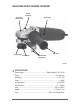
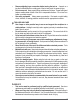
HIGH-SPEED ANGLE GRINDER OVERVIEW Spindle Locking Pin Direction of Rotation Arrow Power Switch Side Handle Locking Flange Inside Flange Protection Guard w/ Clamp Screw Figure-1 SPECIFICATIONS Power Supply........................................................... Single-Phase AC, 50 / 60 Hz Rating ............................................................................................ 115 / 230 Volts Amperage .........................................................................................
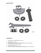
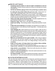
ACCESSORIES (*Available in the 115V and 230V) Figure-2 (**Only available in the 115V) COMPONENTS: 1. 2. 3. 4. 5. 6. 4 Protective Cover w/ Clamp Screw (Part No. 130653) Side Handle (Part No. 130433) Inside Flange and Locking Flange Set with 7/8” Arbor (Part No. 136038 & 136039)* Pin spanner Wrench 34 mm (Part No. 130434) Extra Carbon Brush Set (Part No. 136046) Extra Inside Flange & Locking Flange Set with 20mm Arbor (Part No.
INTRODUCTION Thank you for purchasing the Alpha® High-Speed Angle Grinder. Please read this instruction manual thoroughly to ensure safety and correct use of this tool. Keep this manual in a place where operators can access it easily whenever necessary. ABOUT THE SYMBOLS According to the hazard level, all safety notes in this manual are classified into “DANGER”, “WARNING”, and “CAUTION”. DANGER! Death or serious personal injury is imminent when handling this tool incorrectly.
CAUTION! The following are important notes for products, operation, and maintenance applicable to this High-Speed Angle Grinder. GENERAL SAFETY RULES WORK AREA • Keep your work area clean and well lit. Cluttered benches and dark areas invite accidents. Do not operate power tools in explosive atmospheres, such as in the presence of flammable liquids, gases, or dust. Power tools may create sparks which may ignite the dust or fumes. Keep bystanders, children, and visitors away while operating a power tool.
• • • • • • • • • • • Remove adjusting keys or wrenches before turning the tool on. A wrench or a key that is left attached to a rotating part of the tool may result in personal injury. Do not overreach. Keep proper footing and balance at all times. Proper footing and balance enables better control of the tool in unexpected situations. Do not use on a ladder or unstable support. Use safety equipment. Always wear eye protection.
SPECIFIC SAFETY RULES • • • • • • • • • • • • • Accessories must be rated for at least the speed recommended on the tool warning label. Wheels and other accessories running over rated speed can fly apart and cause injury. Hold tool by insulated gripping surfaces when performing an operation where the cutting tool may contact hidden wiring or its own cord. Contact with a “live” wire will make exposed metal parts of the tool “live” and shock the operator. Know your power tool.
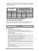
overheating. Below table shows the correct size to use depending on cord length and nameplate ampere rating. If in doubt, use the next heavier gauge. The smaller the gauge number, the heavier the cord.
• Check grinding tools before use. The grinding wheel must be properly mounted and turn freely. Perform a test run for at least 30 seconds without any load. Do not use damaged, out of round or vibrating grinding tools. Immediately switch off the machine in case of considerable vibrations or if other malfunctions occur. Check the machine in order to find out the cause. Always use and store the grinding wheels according to the manufacturer’s instructions.
3. 4. 5. 6. action may decrease the rotation speed which reduces the efficiency of the grinder. Hold the tool with both hands while starting; the torque from the motor will cause the tool to jerk. When the grinding wheel first comes into contact with the work surface or when the wheel is new, make contact slowly. Keep moving the tool in a circular motion to prevent grooving in the work surface. Hold the unit tightly to prevent it from walking, and remove the high spots in the work surface from the top down.
Switching off: OFF POSITION To unlock, depress the back of the sliding switch. The switch will automatically move back as shown in Figure 4. Figure-4 BEFORE USE DANGER! Before using the machine, check the following items. In particular, check items 1 to 5 before plugging the power supply cord into the power outlet. 1. Check the working voltage. – Be sure the voltage specified on the rating plate is the voltage available at the power outlet.
WARNING! 1. Before turning the switch ON, make sure the rotating parts are not touching anything. If the switch is turned ON while they are in contact with anything else, the wheel may get damaged and may cause injuries. 2. When a new wheel is attached and the switch is turned ON, keep your body well away from the exposed sides of the wheel for a moment until the machine reaches its full speed. It is very dangerous to perform grinding operations using cracked, chipped or damaged wheels.
USING THE TOOL PROTECTIVE COVER INSTALLATION CAUTION! The protective cover should be used to prevent the dust and flying debris from hitting the operator or from going inside the tool. Failure to do so can shorten the life of the tool and void the limited warranty. Groove 1. Slide the protective cover onto clamping collar so that the lip on the protective cover fits into the groove on the tool. 2. Position the protective cover with the shield facing backwards as shown in Figure 6.
ASSEMBLING SPINDLE ATTACHMENTS CAUTION! Do not leave threaded accessories on the spindle of the tool for extended periods of time, as this may result in making it difficult to remove these accessories. Note: The Alpha® High-Speed Angle Grinder has a 5/8”-11 spindle thread . It comes with two Inside Flange and Locking Flange sets: 20mm Arbor for 4” discs and 7/8” Arbor for 4-1/2” to 5” discs.
3. While depressing the spindle button, rotate the spindle until the spindle lock button is inserted into the gear, thus locking the spindle in a fixed position. Figure-12 4. With the spindle locked in place, turn the locking flange clockwise until hand-tight. Figure-13 5. Use the 34mm pin spanner wrench to secure tightly. Figure-14 DISASSEMBLING SPINDLE ATTACHMENTS Please follow the reverse procedure for disassembling the working tool from the grinder.
CHECKING AND REPLACING THE CARBON BRUSHES In order to keep the tool running correctly, you need to check the carbon brushes after every one hundred hours of use. Carbon brushes wear out over time based on the grinder’s usage. If a carbon brush is worn out, it may cause the motor to malfunction or fail to run. The carbon brushes should be replaced before the twisted wire reaches the bottom of the slot.
Power Wire Carbon Brush Carbon Brush Assembly Parts Motor Housing Coil Spring Carbon Brush Holder Figure-18 CARBON BRUSH HOLDER REMOVAL 1. Disconnect the power wire from carbon brush holder. Note: Each grinder has 2 carbon brushes located on opposite sides of each other. Figure-19 2. Remove the carbon brush holder from the motor housing by pulling the holder out with a pair of needle nose pliers. 3. With the carbon brush holder removed, you can check and clean the armature commutator.
4. Pictured on the left below, is a worn carbon brush in the holder (Note: the twisted wire is at the end of the slot and the carbon brush is almost flush with holder). On the right below, is a new carbon brush in the holder. Worn and New Carbon Brushes Worn New Figure-21 NOTE: Carbon brushes sometime wear at different rates; however, both carbon brushes should be replaced at the same time.
2. Remove the old carbon brush and disconnect the wire terminal. If the inside of the holder is filled with dust, clean it before installing the new carbon brush. Upon installation of the new carbon brush, make sure the twisted wire is in the slot and behind wire terminals on the holder (as in Figure 22 right photo). 3. With the carbon brush holder removed, you can check and clean the armature commutator. The commutator is the contact points that the carbon brushes ride on when the motor is running.
ALPHA® HIGH-SPEED ANGLE GRINDER SCHEMATIC (HSG-125) 21
ALPHA® HIGH-SPEED ANGLE GRINDER PARTS LIST (HSG-125) DRAWING NO. PART NO. DESCRIPTION PIECES 1 130391 O Ring 16×2 1 2 130390 Lock 1 3 130389 Spring 1 4 130388 Screw M4×7 2 5 130384 Gear Box Assembly 1 6 130458 Needle Bearing HK0709F (7×11×9) 1 7 130450 Snap Ring 13.5×1.2 1 8 130426 Lock Flange 1 9 130420 Small Gear+Oil Wiper 1 11 130442 Big Gear 1 12 130386 O Ring 54×1.5 1 13 130443 Gearbox Cover 2 15 130695 Screw M4×12 4 16 130399 Washer 17.2×30×0.
ALPHA® HIGH-SPEED ANGLE GRINDER PARTS LIST (HSG-125) DRAWING NO. PART NO. DESCRIPTION PIECES 34 136044 Armature Assembly 1 36 130407 Rear Motor Housing (Blue) 1 37 130376 Insulation Disc 1 38 130657 Condenser Assembly 1 39 130381 Ball Bearing 607-2Z (7×19×6) 1 40 130375 Bearing Sleeve 1 41 130027 Self-tapping Screw 3.9 X9.
SERVICES AND WARRANTY INFORMATION LOANER PROGRAM Loaner tools can be issued to temporarily replace a tool that is being returned to Alpha® for repair. If more than one tool is being returned for repair, the number of loaner tools provided will be based on availability. If a loaner tool is required, contact Alpha® Tool Department at (800) 648-7229 to receive a Loaner Tool Application. A valid credit card number must be provided as a security deposit.
ALPHA® TOOL REPAIR SERVICE For more information concerning Alpha® tool repair service, please contact the Alpha® regional repair centers listed below: COMPANY HEADQUARTERS: Alpha Professional Tools® 103 Bauer Drive Oakland, NJ 07436 Hours of Operation: 8:30 a.m. – 5:00 p.m. EST Telephone Number: 201-337-3343 Toll-Free Number: 800-648-7229 Website: www.alpha-tools.
EC DECLARATION OF CONFORMITY Name of Manufacturer: Alpha Professional Tools ® Address of Manufacturer: 103 Bauer Drive Oakland, NJ 07436 USA Herewith declares that: ELECTRIC HAND TOOL: “High-Speed Angle Grinder” Make: Alpha Professional Tools ® Type: HSG-125/HSG-225 -Does comply with the provisions of the Low Voltage Directive 73/23EEC amended by 93/68 EEC and Machinery Directive 98/37/EC.
PRODUCT REGISTRATION CARD Model No. Serial No.
103 Bauer Drive, Oakland, NJ 07436 • 800-648-7229 • Fax: 800-286-0114 www.alpha-tools.com Copyright © 2008 Alpha Professional Tools. All rights reserved.