Alpha-3R Direct Thermal Portable Printer SERVICE MANUAL i
Contents 1. FUNDAMENTAL OF THE SYSTEM ................................ 2 1.1 Overview ........................................................................................................... 2 2. ELECTRONICS ............................................... 3 2.1 Summary of Board Connectors ....................................................................... 3 3. MECHANISM ................................................ 7 3.1 Replacing the Platen Roller (Including media cover) .........................
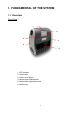
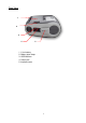
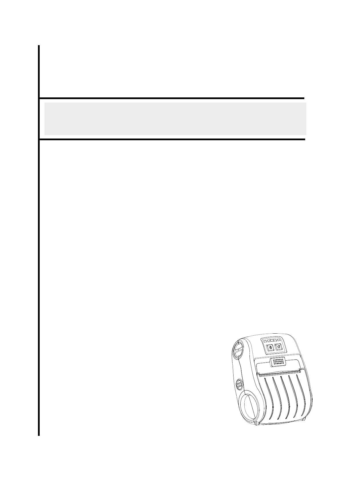
1. FUNDAMENTAL OF THE SYSTEM 1.1 Overview Front View 1 2 3 4 5 6 1. LED indicator 2. Feed button 3. Power on/off button 4. Media cover release button 5. Media holder adjustment knob 6.
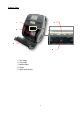
Interior View 2 1 3 4 5 1. Tear edge 2. Print head 3. Media holder 4. Platen 5.
Rear View 1 2 3 4 5 1. Li-ion battery 2. Battery open clasp 3. USB interface 4. Power jack 5.
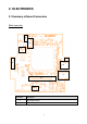
2. ELECTRONICS 2.
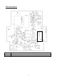
Pin Description 1 3.3V 2 BT/WiFi Reset 3 BT RXD 4 BT RTS 5 BT TXD 6 BT CTS 7 WiFi wake up 8 WiFi TCP 9 BT/WiFi Switch 10 GND Stepping motor 3 Pin Description 1 OUT1 2 OUT2 3 OUT1 4 OUT2 Pin Description 1 3.
Paper sensor 9 5 Pin Description 1 3.3V 2 BM_E 3 BM_R 4 3.
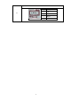
Main board bottom 1 Connector 1 Description Battery connector 6
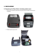
3. MECHANISM 3.1 Replacing the Platen Roller (Including media cover) 1. Remove two screws from the back of the printer and two screws from the front of the printer. 2. Take the printer top cover off.
3. Use a tool to remove the shaft. Remove/Replace the media cover. (including the platen roller ass’y) 4. Reassemble the parts in the reverse procedures.
3.2 Replacing the Keys Control Board 1. Refer to section 3.1 to remove the printer top cover. 2. Remove two screws on the keys control board. 3. Loosen the connector lock then disconnect the flat cable from the keys control board. Remove/Replace the keys control board. 4. Reassemble the parts in the reverse procedures.
3.3 Replacing the Bluetooth Module (Option) 1. Refer to section 3.2 to remove the keys control board. 2. Remove two screws on the Bluetooth control board. 3. Disconnect the connector on the board. 4. Reassemble the parts in the reverse procedures.
3.4 Replacing the Media Holder Assembly 1. Remove two screws and media holder adjustment knob. 2. Take the interior mechanism from the printer bottom cover. 3. Plug the media holder adjustment knob to rotate the media holder to the closest position and remove a screw on the other side. .
4. Take the media holder assembly from the mechanism. 5. Reassemble the parts in the reverse procedures.
3.5 Replacing the Main Board Assembly 1. Refer to section 3.2 to section 3.4 to remove key control board, Bluetooth control board (option), and the media holder assembly. 2. Remove two screws from the back of interior mechanism and disconnect all the connectors on the main board assembly. 3. Reassemble the parts in the reverse procedures.
3.6 Replacing the Print Head Assembly 1. Refer to section 3.2 to section 3.5 to remove key control board, Bluetooth control board (option), the media holder assembly, and main board assembly. 2. Use the long-nose pliers to remove two spring torsions on each side. 3. Take the gear holder and the gear, and push the print head holder on the each side to remove the print head assembly. Gear holder Gear 4. Reassemble the parts in the reverse procedures.
3.7 Replacing the Stepping Motor 1. Refer to section 3.4 and section 3.5 to remove media holder assembly and main board assembly. 2. Remove the gear holder and two gears. Gear holder Gears 3. Remove two screws. 4. Reassemble the parts in the reverse procedures.
3.8 Replacing the black mark sensor assembly 1. Refer to section 3.2 to section 3.5 to remove key control board, Bluetooth control board (option), the media holder assembly, and main board assembly. 2. Remove a screw and replace the black mark sensor. Black mark sensor assembly 3. Reassemble the parts in the reverse procedures.
3.9 Replacing the WiFi Module (Option) 1. Refer to section 3.2 to remove the keys control board. 2. Remove two screws on the board. 3. Refer to section 3.5 to remove the main board assembly. 4. Replace the WiFi control board. 5. Reassemble the parts in the reverse procedures.
4. TROUBLESHOOTING 4.1 Common Problems The following guide lists the most common problems that may be encountered when operating this bar code printer. If the printer still does not function after all suggested solutions have been invoked, please contact the Customer Service Department of your purchased reseller or distributor for assistance. Problem Power indicator does not illuminate Possible Cause Recovery Procedure * The battery is not properly installed. * The battery is dead.
Irregular printing * The printer is in Hex Dump mode. * The RS-232 setting is incorrect. 19 * Turn off and on the printer to skip the dump mode. * Re-set the Rs-232 setting.
5. Maintenance This session presents the clean tools and methods to maintain your printer. 1. Please use one of following material to clean the printer. Cotton swab Lint-free cloth Vacuum / Blower brush 100% ethanol 2. The cleaning process is described as following, Printer Part Method 1. Always turn off the printer before cleaning the print head. 2. Allow the print head to cool for a minimum of one minute. 3. Use a cotton swab and 100% ethanol to clean the print head surface.
Revise History Date 2013/11/4 Content Modify some pictures for label model 21 Editor Camille
TSC Auto ID Technology Co., Ltd. Corporate Headquarters 9F., No.95, Minquan Rd., Xindian Dist., New Taipei City 23141, Taiwan (R.O.C.) TEL: +886-2-2218-6789 FAX: +886-2-2218-5678 Web site: www.tscprinters.com E-mail: printer_sales@tscprinters.com tech_support@tscprinters.com 22 Li Ze Plant No.35, Sec. 2, Ligong 1st Rd., Wujie Township, Yilan County 26841, Taiwan (R.O.C.