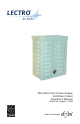
Mini-Mite Ferro Power Supply 30/60Vac Output Operator’s Manual Effective: August, 2003 ® Alpha Technologies
Alpha Technologies Power ®
Mini-Mite Ferro Power Supply — 30/60Vac Output Operator’s Manual Effective: August, 2003 CM003101, Rev. B0 — © 2003 Alpha Technologies NOTE Photographs contained in this manual are for illustrative purposes only. These photographs may not exactly match your installation. NOTE Review the drawings and illustrations contained in this manual before proceeding. If there are questions regarding the safe operation of this powering system, please contact Alpha Technologies or your nearest Alpha representative.
Table of Contents Warnings & Cautions ...................................................................... 5 Unpacking and Inspection ............................................................... 6 1. OVERVIEW 1.1 Introduction ............................................................................ 7 2. SPECIFICATIONS 2.1 2.2 Nominal ................................................................................. 8 General ........................................................................
WARNINGS & CAUTIONS WARNINGS A “Warning” identifies conditions and actions that pose a hazard to the user. NOTE This power supply and its associated hardware (enclosure, cabling) may contain equipment(s), or parts which have accessible hazardous voltage or currents. To avoid injury: • This power supply and its associated hardware must be serviced by authorized personnel only. • Verify AC line power is de-energized prior to installation or service.
Unpacking and Inspection Carefully remove the module or unit from its shipping container. Inspect the contents. If items appear to be damaged or missing, contact Alpha Technologies and the shipping company immediately. Most shipping companies have only a short claim period. Verify the following items have been included: 1. System module or unit 2. Operator’s Manual 3. Any other ordered options Save the original shipping container.
1. Introduction The Lectro Mini-Mite Ferro Power Supply brings the CATV industry a new performance standard. Lectro’s proprietary design provides excellent regulation over varying AC input and load conditions, providing the user with the most efficient and trouble-free ferroresonant system on the market. Careful physical and thermal design ensure a longer life, while allowing chassis replacement with minimum tools and effort.
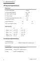
2. Specifications 2.1 Nominal Specifications Electrical AC Input Voltage Range 120Vrms AC Input Voltage Regulation + 10% / -20% AC Output Frequency Range 60Hz AC Output Voltage 60Vrms AC Output Voltage Regulation @ nom. freq. ± 3% Efficiency @ Full Load 80% Output Configurations 2A 4A Input Current, Nominal (Amps) 1.3 2.8 Mechanical 2A 4A Height: in / mm 8.25 / 210 8.25 / 210 Width: in / mm 6.19 / 158 6.19 / 158 Depth: in / mm 4.00 / 102 4.00 / 102 Weight: in / mm 10 / 4.
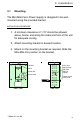
3. Installation 3.1 Mounting The Mini-Mite Ferro Power Supply is designed to be wallmounted using the provided bracket. INSTALLATION PROCEDURE: 1. A minimum clearance of 1.75” should be allowed above, below, and along the sides and front of the unit for adequate cooling. 2. Attach mounting bracket in desired location. 3. Mount on the mounting bracket as required. Slide the Mini-Mite into position on the bracket.
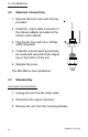
3. Installation 3.2 Electrical Connections 1. Remove the front cover with the key provided. 2. Install the output cable connector in the chassis adapter provided on the bottom of the cabinet. 3. Plug the AC line cord into a 120Vac utility receptacle. 4. If desired, a direct earth ground may be connected using the small copper lug on the bottom of the unit. 5. Replace the cover. The Mini-Mite is now operational. 3.3 Disassembly DISCONNECTION PROCEDURE: 1. Unplug the unit from the utility outlet. 2.
4. Operation 4.1 Changing the output voltage (PSF-MMP-AXX only) The Lectro Mini-Mite Ferro Power Supply is designed to provide regulated 30V or 60V from the 120Vac power line. The power output is normally configured for 60V and can be changed to provide 30V via the following procedure. 60V – 30V CONVERSION PROCEDURE 1. Verify AC is disconnected. 2. Cut yellow wire 2” from end of heat shrink tubing, strip 1/ 2” from end. 3. Remove the wire nut from the blue wire, twist ends of Yellow, Blue wires together.
4. Operation 4.2 Service CAUTION Lethal voltages are present within the chassis when the unit is in operation. For safety, be certain to unplug the input cord and the output cable connector before attempting service. NOTE Part of the unit’s thermal design is heat conduction from the transformer brackets to the cabinet of the power supply. A thin coating of silicone grease is applied to the bracket contact area during manufacture.
4. Operation 4.3 Maintenance Proper operation and longer system life can be ensured by performing the following maintenance: 1. Before opening the cabinet, inspect it for external damage or tampering, including the grounding circuit. 2. Unlock and open the cabinet. 3. Inspect the air vents for obstructions 4. Inspect the connectors and cable for damage or corrosion. 5. Close and relock the cabinet. CM003101 Rev.
Corporate Alpha Technologies 3767 Alpha Way Bellingham, WA 98226 USA Tel: (360) 647-2360 Fax: (360) 671-4936 Web: www.alpha.com Power Alpha Technologies ® Alpha Technologies Ltd. 4084 McConnell Court Burnaby, BC, V5A 3N7 CANADA Tel: (604) 430-1476 Fax: (604) 430-8908 Alpha Technologies Europe Ltd.